Carrier 39B User Manual
Page 11
Attention! The text in this document has been recognized automatically. To view the original document, you can use the "Original mode".
г-
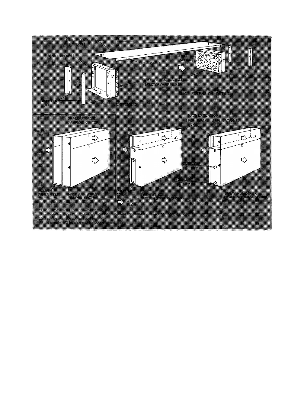
Fig. 8 — Assembly of Accessory Face and Bypass Damper Section; Preheat Coil Section
and/or Spray Humidifier Section with and without Bypass — (Sizes 070-120)
3. Fasten flanges 2 thru 5 of preheat coil or spray
humidifier section without bypass to matching
flanges of cooling coil section with the following:
a.
Fasten flanges 2 and 3 with three
3/8-16
X
3/4-in. hex head cap screws per
two flanges and matching flange weld nuts.
b. Fasten flanges 4 and 5 with three 3/8-16 x
3/4-in. hex head cap screws and hex nuts per
two flanges.
4. Duct extension (for accessories with bypass) —
a.
Preheat coil section only - Remove two
(size 070) or three (sizes 080 thru 120)
1/4-20x1-in. hex head cap screws, plain
washers, and hex nuts from each flange 6
and 7. Save fasteners for following steps b
and c.
b. Place endpiece having largest holes on side
C, on flange 6 of accessory. Face fiber glass
insulated side toward flange 7 of accessory.
Fasten surface A to flange 6 of spray
humidifier section with one 1/4-20 x 1/2-in.
self-tapping screw and flange 6 engagement
hole. For preheat coil section, use two of
each type of fastener saved from preceding
step a.
c.
Place second endpiece on flange 7 of
accessory. Face fiber glass insulated side
toward fiber glass insulated side of first
endpiece. Fasten surface A to flange 7 per
preceding step b.
d. Fasten one angle D to each side E of both
endpieces with two (size 070) or three
(sizes 080 thru 120)
1/4-20 x 1/2-in. self
tapping screws per angle and side E engage
ment holes.
e. Fasten top panel to top of each endpiece
with one (spray humidifier section) or two
(preheat coil section) 1/4-20 x 1/2-in. self
tapping screw(s) per end and engagement
hole(s) in top of each endpiece.
11