Carrier 39B User Manual
Page 15
Attention! The text in this document has been recognized automatically. To view the original document, you can use the "Original mode".
OUTDOOR UNITS — Not recommended for
standard units unless following precautions are
taken into consideration. Consult your local
Carrier representative for units specially factory
equipped for outdoor use.
1. Externally insulate all accessories that are not
factory insulated (combination mixing box and
filter section, filter section, and face and bypass
damper section).
2. If outside temperature will be below dew point
of air in unit at any time during operating
season, insulate complete unit externally to
prevent internal condensation. Vapor seal and
weatherproof insulation.
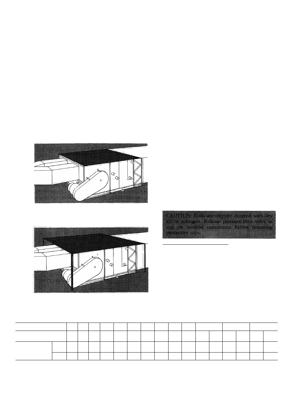
3. Install a crowned waterproof cover on top of
unit to prevent water from collecting or leaking
into unit per Fig. 12. A shed-type cover
(Fig. 13) can be used as an alternate.
Fig. 12 — Crowned-Type Protection Cover —
Field-Supplied
4.
Caulk all joints with nonhardening material
such as butyl-rubber or silicone-rubber to pre
vent moisture infiltration.
5. Install a field-supplied rain shield over outside
air damper of combination mixing box and
filter section.
6. Obtain motor manufacturer’s recommendation
for a fan motor type suitable for outdoor use.
7. Install a field-supphed cover over damper link
age to prevent ice and snow from interfering
with operation. Damper motor must be suitable
for outdoor use.
8. If unit is to be subjected to freezing tempera
tures, insulate condensate drain lines and locate
trap indoors to prevent freeze-up.
9. For coil freeze-up protection, refer to 39B, 39C
Operation and Maintenance Book.
Piping
— Cod connections are labeled on unit.
GENERAL
1. Pipe unit so that vibration is not transmitted to
or from unit.
2.
Allow sufficient clearance for unit piping
connections so that piping will not prevent
removal of fan belt guard.
3. All piping must follow standard piping tech
niques. Refer to Carrier System Design Manual
for details.
DIRECT-EXPANSION COOLING COIL
Fig. 13 — Shed-Type Protection Cover
Field-Supplied
Refrigerant Distributor Nozzles
1.
Check refrigerant distributor nozzle against
design load and note following:
a.
Nozzles installed are for minimum rec
ommended coil loading for proper refrig
erant distribution and oil return. For heavier
loads, proper nozzles must be substituted.
b. Nozzle orifice size is stamped on nozzle.
Refer to Table 5 for factory-installed
standard coil nozzles. Refer to Table 6 for
nozzle orifice capacities.
Table 5 — Factory-Installed Refrigerant Distributor Nozzles — Standard Direct-Expansion Coils
UNIT SIZE
040
050
060
070
080
090
100
105
no
120
130
135
140
Size Coil
In Unit
s
040
050
060
070
080
090
100
130
110
120
130
130
no
130
120
130
Qty-Size
3
Nozzles
In Coil
4- And
6-Row
1-G2
1-G3
1-G4
1-C4
1-C5
2-C5
2-C6
2-C5
2-C6
2-AlO
2-C5
2-C5
2-C6
2-C5
2
-AlO
2-C5
8-Row
1-G2
1-G3
1-G4
1-AlO
1-A12
2
-A
1 2
2
-A
1 2
2
-A
1 2
2
-A
1 2
3-A12
2
-A
1 2
2
-A
1 2
2
-A
1 2
2
-A
1 2
3-A12
2
-A
1 2
1«;