Fig. 7 — low-pressure switch (lps) adjustment, Check capacity control system description, Check capacity control system – Carrier 30H User Manual
Page 9
Attention! The text in this document has been recognized automatically. To view the original document, you can use the "Original mode".
HIGH-PRESSURE SWITCH (HPS)
The
HPS
settings
are
nonadjustable.
Table
5
shows the factory settings for this switch.
If the HPS cuts out while the unit is in normal
operation (2-1/2 minutes or more after compressor
start-up), the compressor will stop and lock out. To
restart the compressor, the ON-OFF control circuit
switch must be manually pressed to OFF and then to
ON. The timer will start, and after approximately
5.5 minutes, the compressor will start under Time
Guard control. If the pressure has not dropped to
the HPS cut-in point (see Table 5), the compressor
will stop again immediately and again lock out.
No
further attempts to restart should be made untd the
trouble is found and corrected. Unless the control
circuit switch is pressed to OFF at this time, the
timer will continue to run for approximately 1-1/2
minutes and then stop.
If the control circuit switch is left at ON, the
control
circuit
remains
partially
energized,
includ
ing the timer relay. Consequently, if the pressure
drops to the HPS cut-in point before restart, the
compressor
overtemperature
protector
(COP)
light
will come on. This should not be cause for alarm in
this case since the light is functional only when the
discharge
temperature
thermostat
contacts
open
during normal unit operation.
:
ì
/
г
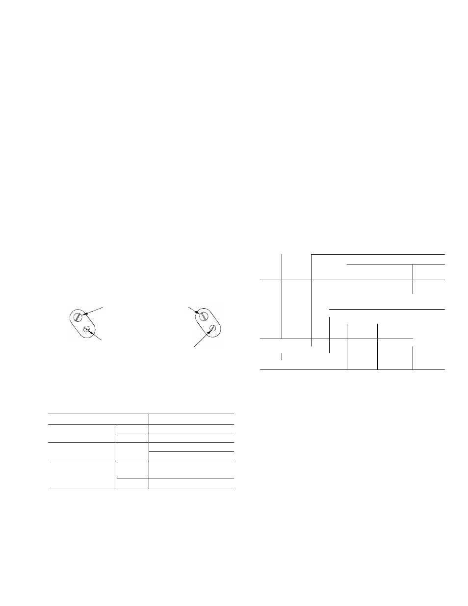
RANGE ADJ SCREW
TURN CLOCKWISE TO RAISE BOTH CUT-IN
AND CUT0UT(7PSI PER TURN),
LPSl
LPS2
DIFFERENTIAL ADJ SCREW
TURN CLOCKWISE TO DECREASE
(8 PSI PER TURN). ONLY CUTOUT CHANGES
(RIGHT SIDE OF CONTROL BOX, VIEWED FROM TOP)
Fig. 7 — Low-Pressure Switch (LPS)
Adjustment
Table 5 — Pressure Switch Specifications
UNIT
зон
PRESSURE
High
Fixed
RANGE (psig)
Low
10 to 90 Adjustable
DIFFERENTIAL
High
103 ±19 (Fixed)
SETTING (psi)
Low
13 to 50 Adjustable
FACTORY
High
Cutout Cut-in
335 ±10 —
SETTING (psig)
Low
29 ±4 1 44 ±4
TOW-PRESSURE SWITCH (EPS)
The
EPS
is
bypassed
for
2-1/2
minutes
after
compressor start on all start-ups.
The EPS has an adjustable range from 10 to 90
psig and a differential of 13 to 50 psi. Table 5 shows
the factory settings for this switch.
If the LPS cuts out while the unit is in normal
operation (any time after 2-1/2 minutes from com
pressor
start-up),
the
timer
starts
and
runs
for
approximately
5.5
minutes.
The
compressor
then
starts, bypassing the LPS for 2-1/2 minutes under
Time Guard® control. If the LPS cut-in pressure is
reached
within
the
2-1/2
minutes,
the
compressor
continues to run; if the required pressure has not
built up, the compressor stops at the end of the 2-1/2
minutes and locks out.
Further attempts to restart the unit must not be
made until the trouble has been found and cor
rected.
The LPS contacts must be closed before the
compressor can be restarted after lockout.
Check Capacity Control System
DESCRIPTION
Capacity control is a system which loads and
unloads compressor cylinders and starts and stops
the compressors to maintain load requirements. The
system
includes
a
4-step
temperature
controller
and cylinder unloaders (see Table 2). Table 6 shows
the capacity control steps.
Table 6 — Capacity Control Steps
SEOUENCE1
SEQUENCE 2
UNIT
CONTR
%
Cap.
Oper Cyl
f
Oper Cyl
ЗОН
STEPS
Tot.
Ckt
Í
Ckt
1 1 2
Cap.
j
Tot.
Ckt i Ckt
1 1 2
1
25
2
2 i —
25 i 2
— i
2
040
2
50
4
2 ; 2
50 i 4
2 ! 2
3
75
6
4 : 2
75 6
2 1 4
4
100
8
4 ; 4
100 : 8
4 ; 4
1
40
4
4 : —
20 : 2
^ ! 2
050
2
60
6
4 , 2
60 : 6
4 : 2
3
80
8
6 ; 2
80 ^ 8
4
i
4
4
100
10
6 i 4
100 10
6 i 4
1
33
4
4 : —
33 1 4
— i 4
060
2
67
8
4 : 4
67 М 8
4 4
3
83
10
6 М 4
83 1 10
4 : 6
4
100
12
6
1
6
100 ! 12
6 ) 6
4-STEP
TEMPERATURE
CONTROLLER
This
controller
consists
of
4
load
switches
actuated by pressures developed in a temperature
sensing bulb located in the return water line of the
chilled water system. The controller is factory set to
control from
return water temperature thru a cool
ing
range
of
10
F.
The
sequence
switches
are
factory calibrated and sealed and should not require
any field changes.
I MPtJR I .AN I: If a different return-water cool
ing range or lea\'in^-\\.atcr control is specified,
or if brine below 10 F'i.s to be used, the controller
must be changed. Consult local Cai’rier rep
resentative for proper control device.
The return water temperature at which the last
step of capacity unloads is indicated by the leaving
water temperature design setpoint on the adjustable
dial (Fig. 8).