Attempt, For a, The problem – Carrier 30H User Manual
Page 8: Been, Corrected
Attention! The text in this document has been recognized automatically. To view the original document, you can use the "Original mode".
FOUR FUNCTION TIMER
Refer to Fig. 4 — Timer Cycle. The functions are
as follows:
Switch A (Contacts A-Al, A-A2) runs the timer
motor. This provides a minimum of 5-1/2 minutes
after the compressor stops before it can restart, to
prevent short cycling (Time Guard® control).
Switch B (Contacts B-Bl, B-B2) provides 1-second
time delay for part-winding start and also provides a
lock-out function.
Switch D (Contacts D-D 1) provides a 2-1 / 2 minute
bypass of the low-pressure switch at start-up to
prevent nuisance trips under cold-start conditions.
Switch
E
(Contacts
E-El)
provides
a
35-second
bypass of the oil safety switch (OPS) at compressor
start-up (when OPS is used). If sufficient oil pressure
does not build up in this time, the compressor stops.
POSITION DURING UNIT OPERATION,
0 OR 8 MIN,
!
!
DD2 1
------ 2-6
SEC 1
--------------------- 150
SEC^-^
----------------
— +
-55 MIN-
NOTE:
black
DENOTES CLOSED CONTACTS
Fig. 4 Timer Cycle
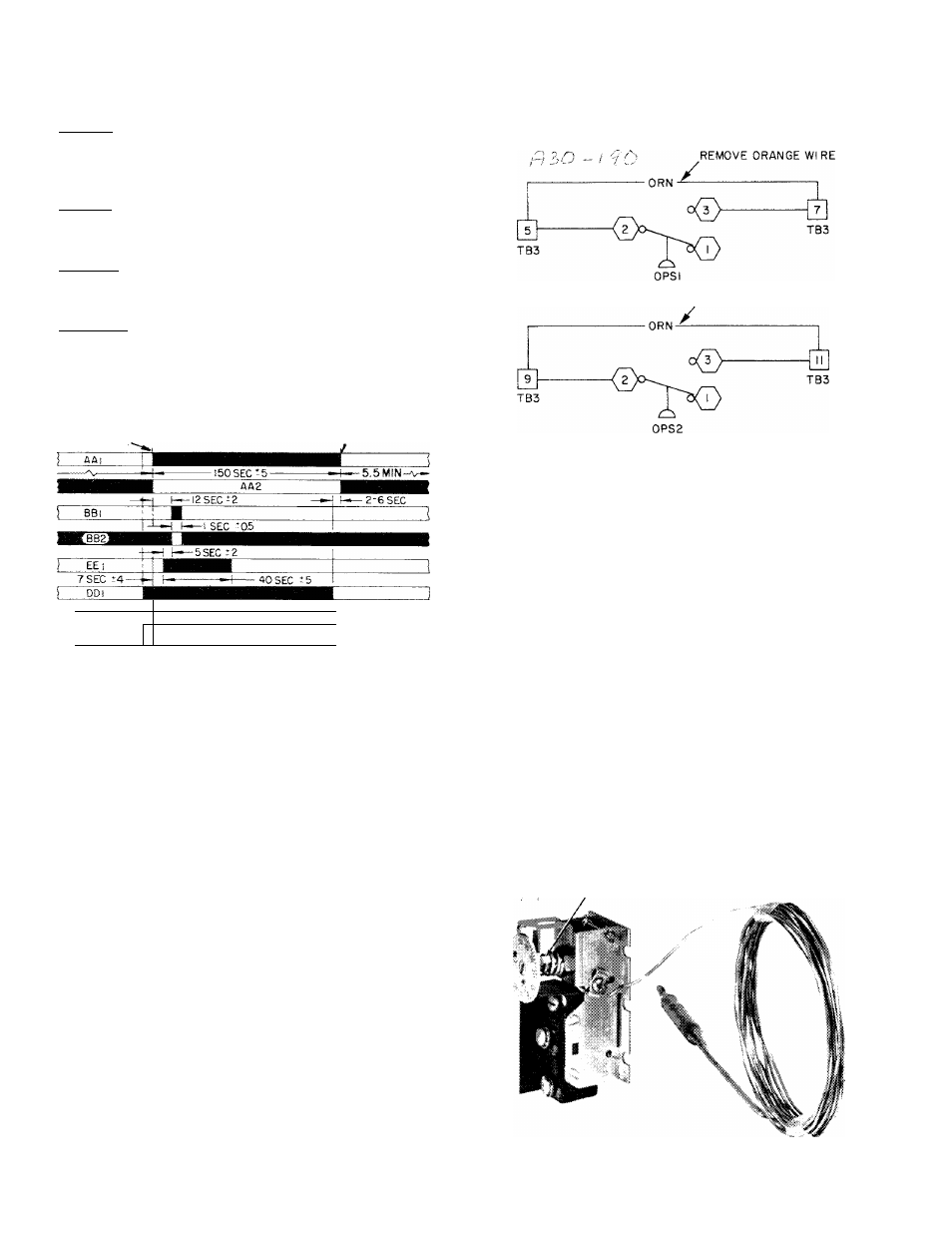
OIL PRESSURE SAFETY SWITCH (OPS)
This control is available as an accessory. Refer to
Fig. 5 for field wiring connections.
The pressure switch is factory set at the following
pressures and should not be adjusted in the field:
SWITCH POSITION
Close on rise
Open on fall
PRESSURE SETTING
9-12 psi diff
4- 6 psi diff
The oil pressure safety switch is wired in parallel
with Switch E of the 4-function timer. This arrange
ment
allows
approximately
35
seconds
for
oil
pressure to reach normal operating level after com
pressor start. If the oil safety switch does not close
within 35 seconds, the compressor shuts down.
To
restart
the
compressor,
the
control
circuit
ON-OFF switch must be pressed to OFF and then to
ON. The timer will start and after approximately
5.5 minutes the compressor will start. If normal oil
pressure is established within the next 35 seconds,
the compressor continues to run. If, however, the oil
pressure does not reach a safe level, the compressor
stops at the end of the 35 seconds and locks out.
CAUTION; Do not
attempt
to restart the com
pressor
for a
second time until
the problem
has
been
determined and
corrected.
REMOVE ORANGE WIRE
OPS — Oil Pressure Safety Switch
TB — Terminal Board
Fig. 5 — Oil Pressure Safety Switch to Control
Box Wiring Connections
Check Unit Safety Devices
SAFETY THERMOSTAT (Fig. 6)
This low water temperature cutout (LWTC) pro
tects the unit against freeze-up due to operating
malfunction. The sensing bulb is inserted into a well
located in the
leaving water nozzle. As installed, the
standard control is factory set to open at 36 ±2 F,
breaking the control circuit and locking out the unit.
The contacts remake at 5
+ 2 F above the cutout
point, but the control circuit switch must be pressed
to OFF and then to ON for unit restart. This action
reenergizes the control circuit and starts the timer
under Time Guard® control.
The thermostat is designed to cut out in a range
down to -30 F, but to obtain this range, the low-limit
stop tab on the underside of the dial must be either
cut or bent.
Make this adjustment only if necessary
(when cooling glycols or brines).
n u
LOW LIMIT STOP TAB
f
Fig. 6 — Safety Thermostat
(No. HH22CC050 Shown)