Carrier 30H User Manual
Page 4
Attention! The text in this document has been recognized automatically. To view the original document, you can use the "Original mode".
CAUTION; Retìghten all condenser head bolts
before filling system with water. Torque bolts
to 150-170 Ib-ft.
Water leaving condenser is under pressure and
should not be connected directly into sewer lines.
Check local codes. A 3/8-in. drain plug is located in
the head at each end of the condenser.
Refer to Pressure Relief Devices concerning con
nections for these components.
COOLER DESCRIPTION
The cooler is a direct-expansion type with remov
able heads and is partitioned for multi-pass refrig
erant flow. The water flow across the tube bundle
is directed by baffles designed for minimum water-
pressure drop. The tubes have integral internal fins
for maximum heat transfer efficiency.
Viewed from the front of the unit, the chilled
water enters (returns) at the left end of the cooler and
leaves at the right end. The sensing bulb for the
factory-set
water
temperature
controller
is
located
in the return-water nozzle; the return-water tem
perature being the control point. The sensor for the
low
water-temperature
cutout
is
located
in
the
leaving water nozzle.
The cooler is insulated with a flexible, closed
cell
plastic
foam
insulation
of
suitable
thickness.
Water vapor cannot penetrate the cellular structure
to condense either within the cells or on the cooler
shell. Thus, the insulation itself is a vapor barrier.
Because of the toughness of the insulation, a pro
tective sheet metal covering is not necessary.
The standard cooler can be used for all glycol
brines down to -20 F. However, for calcium or
sodium
chloride
brines,
it
is
important
that
the
proper inhibitors be carefully selected for protection
of the copper tubes. Refer to publications of the
Calcium Institute or the Mutual Chemical Division
of
Allied
Chemical
Corporation
for
information
on corrosion control in calcium or sodium chloride
systems.
COOLER PIPING
Plan piping for minimum number of changes in
elevation. Install manual or automatic vent valve at
high points in line. Maintain system pressure by
using a pressure tank or combination relief and
reducing valve.
See
Carrier
System
Design
Manual,
Part
3,
Piping Design, for chilled water piping detials.
Install
thermometers
in
entering
and
leaving
water lines. Provide drain connections at all low
points
to
permit
complete
drainage
of
system.
Connect shutoff valve to drain line before operating
unit.
Install
shutoff
valves
near
entering
and
leaving
water
connections.
Use
flexible
connections
to reduce vibration transmission.
Insulate piping
after leak testing to prevent heat
transfer and sweating. Cover insulation with mois
ture seal.
All field wiring must conform with local code
requirements.
Control
circuit
is
115
volts
on
all
60-Hertz
units.
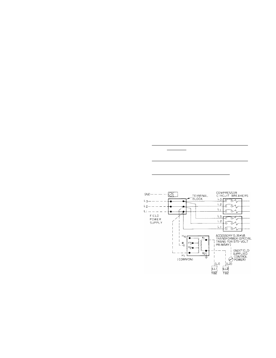
Accessory
transformer
package
is
available to allow 115 volts to be taken directly from
unit terminal block (see Fig. 3). Installation instruc
tions are furnished with the accessory package. Con
trol power may also be supplied from a separate
source thru a 15-amp fused disconnect.
Inside
the
control
box,
provision
is
made
to
connect the ground wire which must be installed
with each field power supply.
All units are factory supplied with across-the-line
start at all voltages.
Refer to Table 4 for electrical data on individual
compressors
and
complete
units
and
compressor
usage.
LABEL DIAGRAMS
The applicable Label Diagrams for the 30H040,
050,060 Heat Reclaim units are the same as for the
standard 30HK040,050,060 units.
Table 3 — Unit Voltage and Model Number
Step 5 — Make Electrical Connections
UNIT
30H
VOLTS
230 i
Model*
460
575
200
.....
040
! 420
: 520 1
620
120
050
i 420
520 ‘
620
> 120
060
420
520 I
620
120
*Last 3 digits of complete mode! number.
EQUIP GND
WHEN CONTROL CIRCUIT POWER IS FROM SEPARATE SOURCE
INCOMING WIRES ARE CONNECTED DIRECTLY TO
TERMINALS
LL!
AND
LL2
ON TB2.
±2
MUST BE
CONNECTED TO NEUTRAL (GROUND) POTENTIAL.
CB
— Circuit Breaker
EQUIP GIMD — Equipment Ground
TB
— Terminal Board
*Appropriate
transformer
terminal
depends
on
unit
voltage,
instructions with accessory transformer package. H2 = 200 v;
H3 = 230 v; H4 = 460 v.
NOTE: For grounding 1 1 5-voit control circuit when transformer is
used, see instructions with accessory transformer package.
Fig. 3 — Wiring Schematic — Unitand Control
Power Supply