Unit operation, Servicing the cooler, Servicing the cooler ,12 – Carrier 30H User Manual
Page 11
Attention! The text in this document has been recognized automatically. To view the original document, you can use the "Original mode".
UNIT OPERATION
Control Power
(115 volts) can be from a separate
source, thru a 15-amp fused disconnect or can be
taken from the main unit power source, thru a field-
supplied transformer as shown on the wiring label.
Control Sequence
— At initial start-up, assume
all safety devices are satisfied and the chilled water
temperature controller switches are all in position
for maximum cooling capacity.
Close the compressor circuit breaker and press the
control circuit ON-OFF switch to ON. Timer no. 1
starts and, depending on the position of the timer,
compressor no. 1 starts in approximately 12 seconds
to 8 minutes. At compressor start-up, the D-D 1 con
tacts
(see
Four-Function
Timer
and
Fig.
4)
are
closed, bypassing the low-pressure switch for 2-1/2
minutes. In addition, the E-El contacts are closed,
bypassing the oil safety switch (if used) for approxi
mately 35 seconds. Both these bypass functions are
protection against the compressor continuing to run
under conditions that could cause damage to the
compressor.
Barring
any
malfunction,
when
the
timer
contacts
A-A2
close,
approximately
2-1/2
minutes after start-up, timer no.
I
stops and timer
no. 2 starts. In approximately 12 seconds to 8 min
utes, compressor no. 2 starts. Timer no. 2 completes
the same cycle as timer no. ! and stops. Unit is now
in
normal
operation,
with
both
compressors
running.
The temperature controller regulates the cooling
capacity by loading and unloading compressor cyl
inders and stopping and starting the compressors
under Time Guard® control, in response to load
requirements.
Complete Unit Stoppage and Restart
— After
each possible cause for unit stoppage is a short
description of the normal method of restart.
1. CONTROL POWER INTERRUPTION (IN
CLUDES BLOWN FUSE).
After power is restored, or fuse replaced, restart
is automatic thru normal timer cycle.
2. CONTROL CIRCUIT ON-OFF SWITCH IS
OPENED.
When the switch is opened, the timer motor starts
automatically,
runs
for
approximately
5-1/2
minutes
and
stops.
To
restart,
press
ON-OFF
switch to ON. In approximately 12 seconds, com
pressor starts.
3. CONTACTS OF ANY AUXILIARY INTER
LOCK ARE OPEN.
After trouble has been corrected, restart is auto
matic thru normal timer cycle.
4. LOW WATER TEMPERATURE CUTOUT
CONTACTS ARE OPEN.
Allow water temperature to rise 5 F; then press
control circuit ON-OFF switch to OFF and back
to ON. This restarts the timer. Unit restarts auto
matically thru normal timer cycle.
5. CONTROL CIRCUIT FUSE BLOWS.
Check for possible cause; then replace fuse. Re
start is automatic thru normal timer cycle.
6. CHILLED WATER FLOW STOPS.
Locate
and
correct
cause.
When
water
flow
resumes, unit restart is automatic thru normal
timer cycle.
Individual Compressor Stoppage and Restart
1. LOW-PRESSURE SWITCH (LPS) OPENS.
Reset
and
restart
are
automatic,
thru
normal
timer cycle, unless refrigerant charge is very low
or lost. In this case, increase the charge to
normal level before restart.
2.
HIGH-PRESSURE
SWITCH
(HPS)
OPENS.
Press
RESET
button
to
reenergize
the
open
circuit. Restart is thru normal timer cycle.
3.
DISCHARGE
TEMPERATURE
SWITCH
OPENS.
Press
RESET
button
to
reenergize
the
open
circuit. Restart is thru normal timer cycle.
4.
OIL
PRESSURE
SAFETY
SWITCH
OPENS.
Press
RESET
button
to
reenergize
the
open
circuit. Restart is thru normal timer cycle.
IMPORTANT:
If stoppage by
a
safety device
repeats
once,
do
not
attempt
another
restart
until
the cause is
determined and corrected.
Refer
also
to
the
Troubleshooting
section
for
additional information on unit malfunctions.
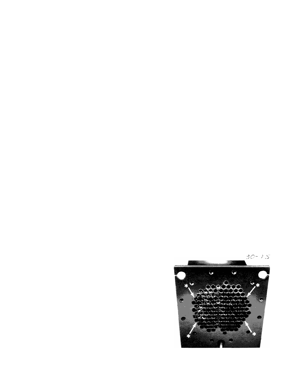
SERVICING THE COOLER
When the cooler heads and partition plates are
removed, the tube sheets are exposed showing the
ends of the tubes as seen in Fig. 11. Four tubes in
the bundle are secured inside the cooler at the
baffles and
cannot be removed. These are identified
on the tube sheets by a drill mark horizontally
adjacent to each of the 4 tubes.
If leakage occurs in
any of these 4 tubes, plug the tube as described under
Tube Plugging.
‘Four fixed tubes (cannot be removed) identified by adjacent
drill points.
Fig. 11 — Typical Tube Sheet
1 1