High pressure switch, Front, 240, 160 a 100 lb. bins – Carrier 26H User Manual
Page 51: Carrier
Attention! The text in this document has been recognized automatically. To view the original document, you can use the "Original mode".
Carrier
S E R V I C E
26H
#
WITH PARTITION
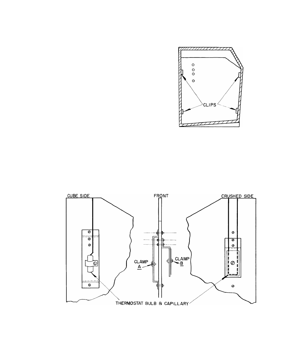
Attach brackets to partition as shown in Fig. 33
and install the partition, Fig. 34. Run the capillary
along the top of the bin liner, down the crushed
ice side of the partition and then over the top of
the partition to the cube side.
31. HIGH PRESSURE SWITCH
This switch stops the unit if the head pressure ex
ceeds 220 - 7 PSIG. It is located in the same
casing as the bin thermostat. This cut-out point
is set at the factory and cannot be changed in the
field.
N O T E : On start up the unit may cycle on and off
several times due to high head pressure. This is
normal. The number of times the unit cycles can
be decreased by turning the unit to "pump" for a
half minute and then restarting.
FRONT
FIG. 33 - SKETCH SHOWING BRACKET
ATTACHED TO PARTITION
In replacing this switch the entire control must be
changed. Pump down the compressor as explained
in Section 4.
240, 160
a
100 LB. BINS
FIG. 34 - SHOWING PARTITION INSTALLED IN BIN
51
26H-57PD