Carrier – Carrier 26H User Manual
Page 35
Attention! The text in this document has been recognized automatically. To view the original document, you can use the "Original mode".
Carrier
S E R V I C E
26H
«
N O T E F O R M E D P R O J E C T I O N
F O R S P A C I N G S P R E A D E R
W A T E R
S P R E A D E R
I N P O S I T I O N
W A T E R
S P R E A D E R
R E M O V E D
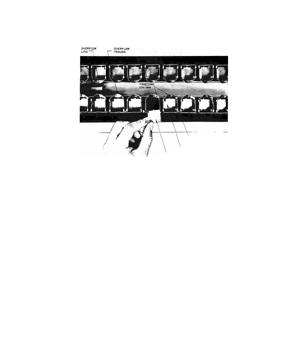
FIG. 17 - WATER SPREADER PLATES
3. During the period of "Blowing the charge", re
move screws and clamps from each side of
lower evaporator shroud, then lift shroud up
wards as far as it will go. Capillary joints
are accessible on right side of unit.
4. Remove water distributor header.
5. After refrigerant charge is "blown", carefully
melt capillary, suction header and hot gas
header joints. Pull joints apart while applying
heat. On the left side of evaporator, melt
water trough overflow and safety overflow
which are "soft solder" joints and require
very little heat.
C A U T I O N : The capillary suction header and hot
gas header joints are Phos-copper which melts at
approximately 1400°F. Care should be taken not
to "over-heat" the Phos-co joints when melting or
making a connection.
6. Remove evaporator support bracket screws and
lift evaporator straight up.
7. Remove all spreader plates. Remove all scale
and clean. Place spreader plates in new
evaporator assembly.
8.
Position replacement evaporator in unit;
fasten supporting brackets.
9. Make all connections. If Phos-co is not avail
able, silver solder maybe substituted. Pliers
may be used to guide capillary in place while
soldering. Make sure that no hard solder plugs
capillaries.
10. Fasten water header in place.
11. Check oil level of compressor. Refer to Sec
tion 6.
12. Evacuate the refrigerant system. Refer to Sec
tion 8.
13. Add refrigerant to system. Refer to Section 4.
14. Machine must be operated for many cycles to
check freezing and defrost time. While unit is
operating, check for refrigerant leaks. When
unit is satisfactory, replace evaporator shrouds
and panels.
15. When replacing the evaporator assembly, the
operation of the main control thermostat and
the safety overflow switch must be checked.
35
26H-57PD