Carrier – Carrier 26H User Manual
Page 30
Attention! The text in this document has been recognized automatically. To view the original document, you can use the "Original mode".
26H
S E R V I C E
Carrier
Portable Line Voltage Tester
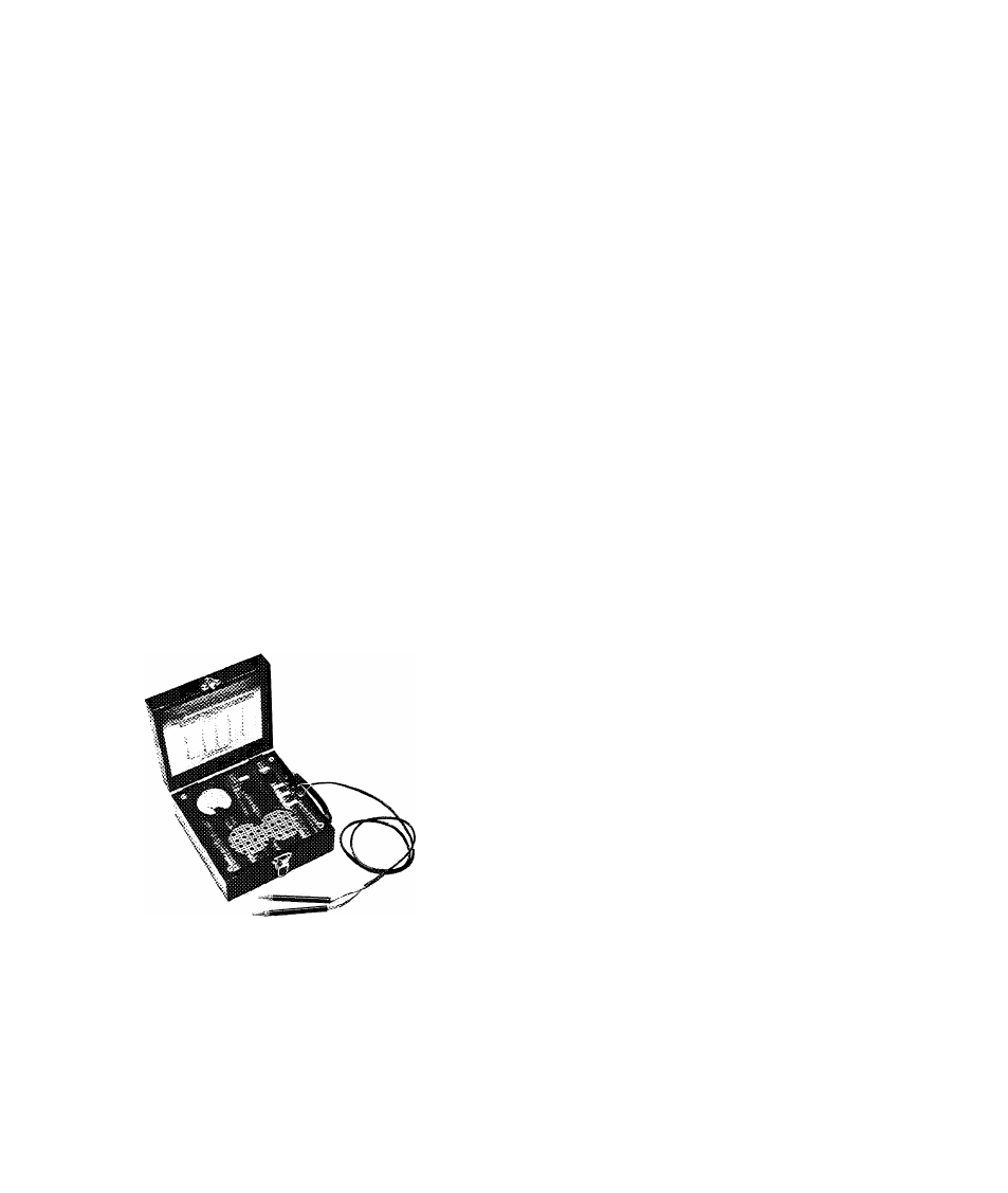
APPLICATION AND OPERATION - A portable line
voltage tester with built-in phantom load which
provides a simple means of checking single phase
or direct current circuits is shown in Fig. 14. By
reading the voltage at no load and the voltage with
phantom load it can be determined if the circuit is
adequate for starting and operating the unit. The
tester is made to Carrier specifications and includes
a table for use with ice cube makers.
PHYSICAL DATA
Case Size
Voltmeter Scale
Ampere Load
Voltage
F requency
Approx. Weight
8"x 8"x 4"
0-150 volts (Double Reading for
230V)
11.5
115 - 230
25, 50, 60 cycles or direct current
5 pounds
Order Directly from
J. & W. Company 290 Roycroft Blvd., Buffalo 21, N.Y.
FIG. 14 - VOLTAGE TESTER
COMPRESSOR REPLACEMENT 26H3
To replace the compressor use the following pro
cedure:
1. Purge the refrigerant charge and then front-
seat both shutoff valves. Disconnect the suc
tion line flare nut at the shutoff valve. Seal
the suction line with a 1/2" plug to prevent
moisture from entering the system.
2. Cut the discharge line and sweat in a 1/4"
SAE male copper to flare connection. Cap this
connection to prevent moisture from entering
the system.
3. Disconnect the compressor leads at the se
lector switch and thermostat.
4. Remove the four compressor mounting bolts
and lift the compressor from the unit.
5. Seal all openings on the compressor to pre
vent moisture from entering prior to repair or
exchange.
6. If compressor failed due to motor burnout, see
"Replacement After Motor Burnout".
7. Install the replacement compressor. The re-
placemsat compressor is shipped with the dis
charge line fastened to the suction shutoff
valve gauge portby means of a 1/4" flare nut.
8. After completing all wiring and piping con
nections evacuate and purge the replacement
compressor.
9. Charge the unit with refrigerant 12. See Sec
tion 4.
10. Before leaving the unit check for leaks.
COMPRESSOR REPLACEMENT 26H5
To replace the compressor, follow this procedure:
1. If the compressor is in running condition,
pump down as explained in Section 3.
•2. If the compressor is not in running condition
close the suction, discharge and oil return
shutoff valves and then slowly bleed pressure
thru the discharge gauge plug.
3. Check to see that both shutoff valves are
f rontseated and unbolt them from the com
pressor. Leave the valves connected to the
piping.
4. Disconnect the high pressure line from the
discharge side of the compressor.
5. Close the water supply valve and disconnect
the compressor cooling coil. The replacement
compressor comes supplied with this coil.
26H-57PD
30