Refrigerant circuit, L shutoff valves, Carrier – Carrier 26H User Manual
Page 23
Attention! The text in this document has been recognized automatically. To view the original document, you can use the "Original mode".
Carrier
S E R V I C E
26H
~w
#
REMOVING THE PANELS
To remove the top front panel turn both handles so
they are horizontal and lift it out. To remove the
top panel remove the screws shown in Fig. 5. Tilt
the panel up and back to disengage it from the back
panel. The side panels are held in place at the
front by two screws and the bottom front panel. The
side panels engage with the flanged edge of the
back panel. Do not remove the back panel except
when absolutely necessary. It is held in place by
six screws threaded into the frame.
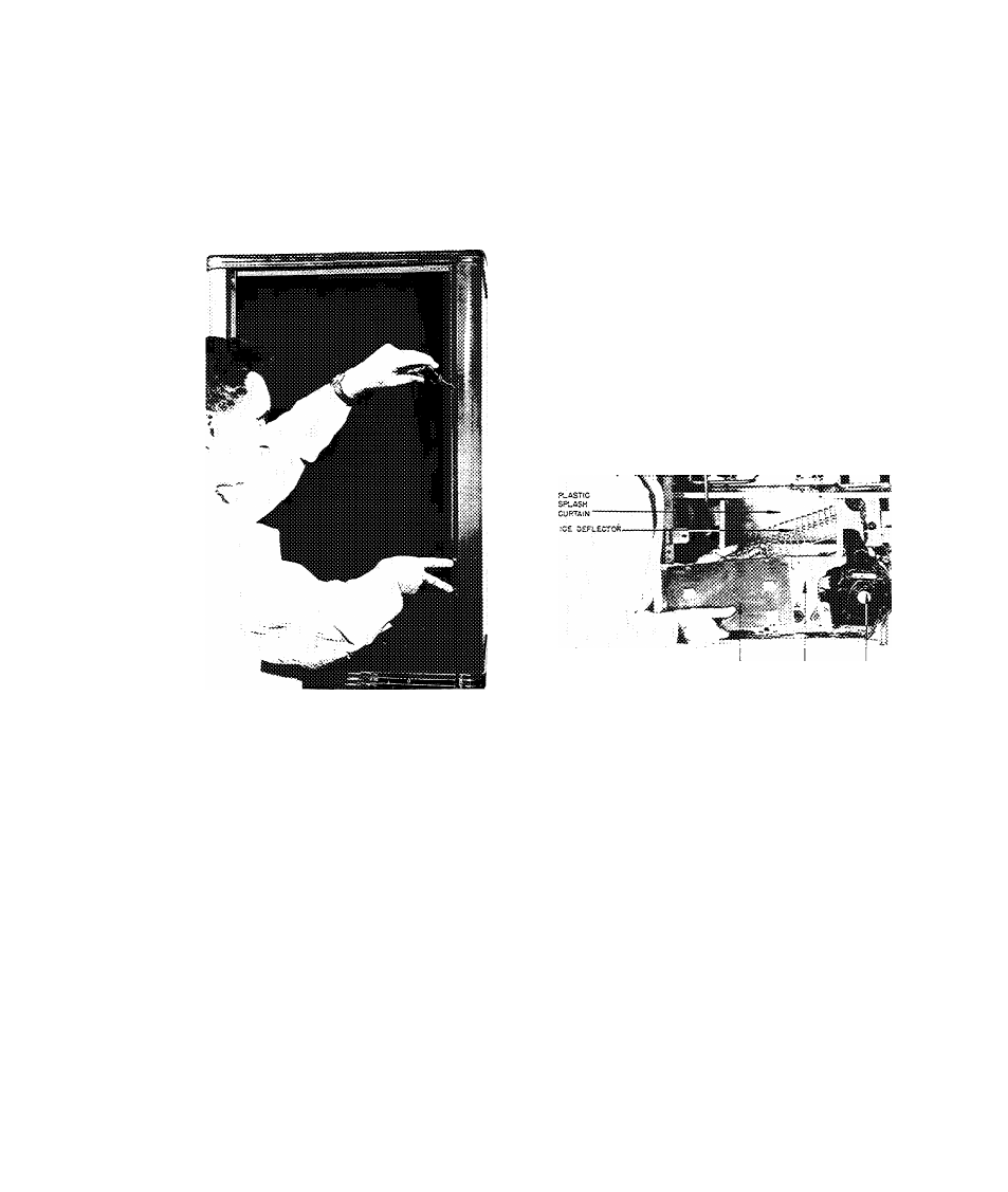
Cleaning and inspecting can be done by removing
the front access door, splash curtain, and ice de
flector screen. The plastic curtain is riveted to a
cross arm held in place by two screws (Fig. 6).
After inspection and cleaning, be sure to reposition
the plastic curtain properly to prevent water from
splashing into the bin. (Fig. 7).
ACCESS DOOR ICE CRUSHER CRUSHER
MOTOR
FIG. 5 - REMOVING SCREWS HOLDING TOP
AND SIDE PANELS
FIG. 6 - REMOVING ACCESS DOOR AND
ICE DEFLECTOR
2. REFRIGERANT CIRCUIT
L SHUTOFF VALVES
Fig. 8 is a cross sectional view of a shutoff valve
in mid-position. When the unit is shipped all valves
are backseated and should be left so during normal
operation. A brass cap and gasket cover the valve
stem to prevent leaks. The gauge ports are plugged
with two 1/8" MPT plugs.
26H3
There are two shutoff valves in the circuit - a suc
tion valve and a discharge valve. (See Fig. 9).
26 H5
There are three shutoff valves in the circuit - a suc
tion valve, discharge valve, and oil return valve.
(See Fig. 10).
23
26H-57PD