N. bolt tie bar at rear of unit, Install water supply and drains, Fig. 8 - parts shipped on back of machine section – Carrier 26H User Manual
Page 12: Installation, Carrier
Attention! The text in this document has been recognized automatically. To view the original document, you can use the "Original mode".
INSTALLATION
Carrier
^1^
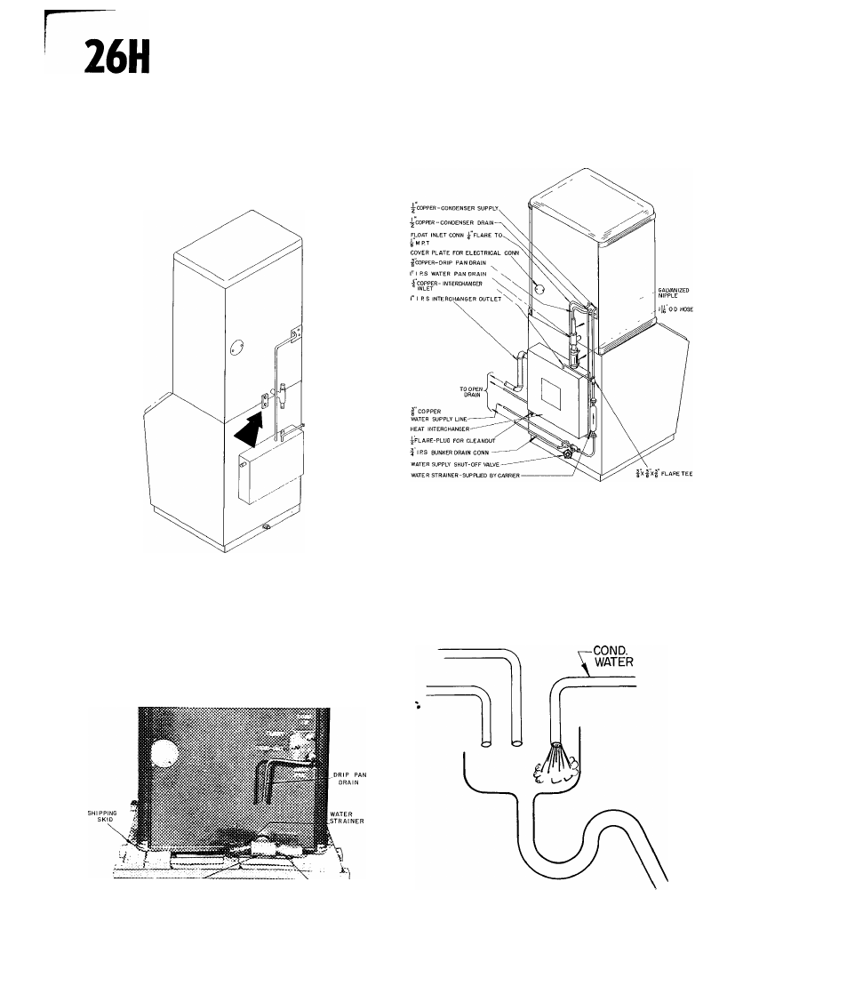
n. BOLT TIE BAR AT REAR OF UNIT
Lock the two sections together with the tie bar
shipped on the back of the machine section. See
Fig. 7.
FIG. 7 - BOLTING TIE BAR AT REAR OF UNIT
12. INSTALL WATER SUPPLY AND DRAINS
Fig. 8 shows the piping connections and parts sup
plied by the factory. Any approved source of drink
ing water can be used provided a 30-60 lb. water
pressure can be maintained. If the pressure ex
ceeds 60 lbs. a pressure reducing valve must be
used.
r 6ALVAN12ED"T
GALVANIZED NIPPLE
FIG. 8 - PARTS SHIPPED ON BACK OF
MACHINE SECTION
Refer to Fig. 9 for recommended piping details.
FIG. 9 - PIPING DIAGRAM
The drain lines should be piped separately to an
open drain. The bin drain must be pitched down
ward for gravity flow. See Fig. 10.
f
FIG. 10- OPEN DRAIN
26H-57PD
12