Installation, Carrier, Uncrate the bin – Carrier 26H User Manual
Page 10: Install leveling screws, Unpack and mount the heat interchanger, Installation -i8
Attention! The text in this document has been recognized automatically. To view the original document, you can use the "Original mode".
26
H
INSTALLATION
TABLE 3 - CRATED DIMENSIONS
Carrier
Height
Depth
Width
Weight
(in.)
(in.)
(in.)
(lb.)
26H5 Machine Section
43-1/2
23-1/2
28-1/2
307
26H3 Machine Section
43-1/2
23-1/2
28-1/2
236
100 lb. Bln
31-1/2
27
26
95
160 Lb. Bin
39-1/2
26-1/2
25
112
240 Lb. Bin
39-1/2
26-1/2
35
142
500 Lb. Bin
45-1/2
34-7/8
49-1/2
225
Heat Interchange!
22-1/2
17
5
18
4. UNCRATE THE BIN
Uncrate the bin first since it serves as the base
for the unit.
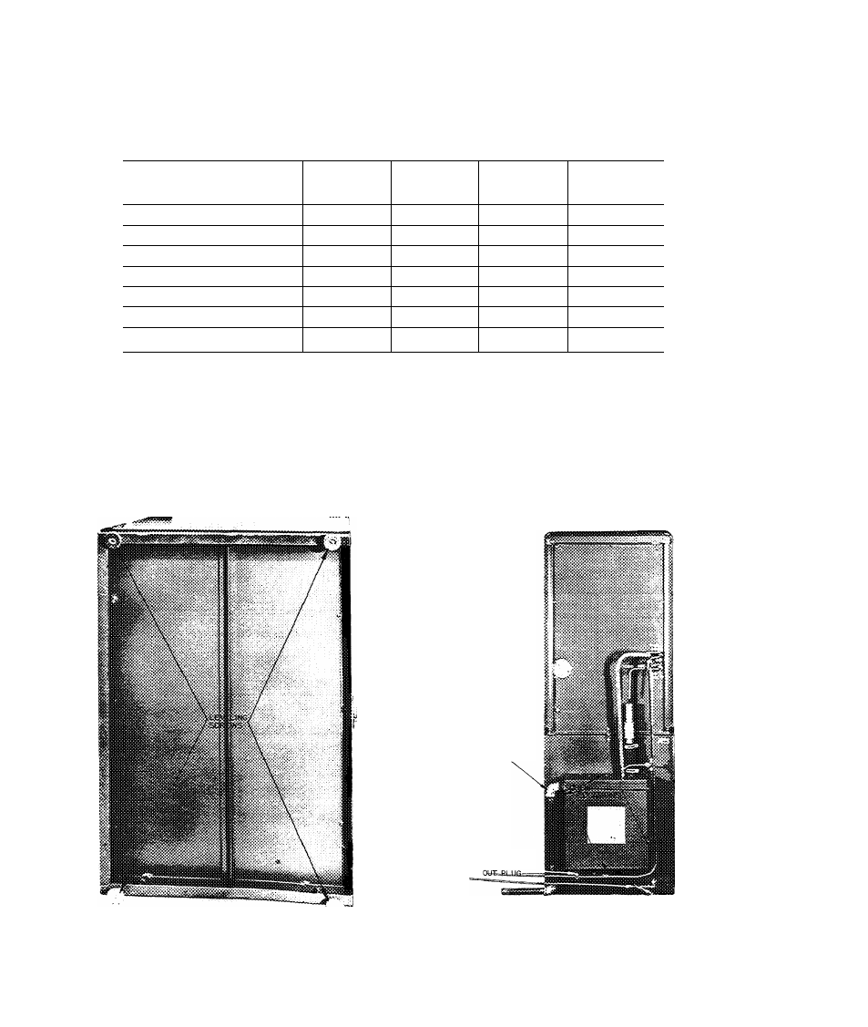
5. INSTALL LEVELING SCREWS
Support the bin with the four leveling screws sup
plied with the bin. See Fig. 1. The top of the bin
can be used for leveling.
6. UNPACK AND MOUNT THE HEAT
INTERCHANGER
Remove the interchanger and parts from the carton.
Mount the heat interchanger on the back of the bin
with the 6 sheet metal screws in the paper envelope.
The position of the interchanger on the back of the
bin is shown in Fig. 2.
HEAT INTERCHANGER
DRAIN
HEAT INTERCHANGER
CLEAN
t
FIG. 1 - LEVELING SCREWS INSTALLED
FIG. 2 - POSITION OF HEAT INTERCHANGER
ON THE BIN
26H-57PD
10