Carrier 48HDT User Manual
Page 21
Attention! The text in this document has been recognized automatically. To view the original document, you can use the "Original mode".
If Chargemaster® charging device is used, tem
perature and pressure readings must be accom
plished using the charging chart.
Main and Pilot Burners — At the beginning of
each heating season, inspect for deterioration or
blockage due to corrosion or other causes. Observe
the pilot and main burner flames and adjust, if
necessary, referring to automatic Pilot Adjustment
or Main Burners sections of instructions.
Flue Gas Passageways — Inspect flue collector
box and upper areas of heat exchanger cells by
removing burner compartment access panel; then
remove flue cover and inspect heat exchangers.
Using a wire brush, clean all surfaces as required.
Combustion Air Blower — Clean periodically to
assure proper airflow and heating efficiency. Inspect
blower wheel every fall and periodically during
heating season. For the first heating season, inspect
blower wheel bimonthly to determine proper clean
ing frequency.
To inspect blower wheel, remove draft hood and
screen. Shine a flashlight into opening to inspect
wheel. If eleaning is required, remove motor and
wheel as follows:
1. Remove burner access panel.
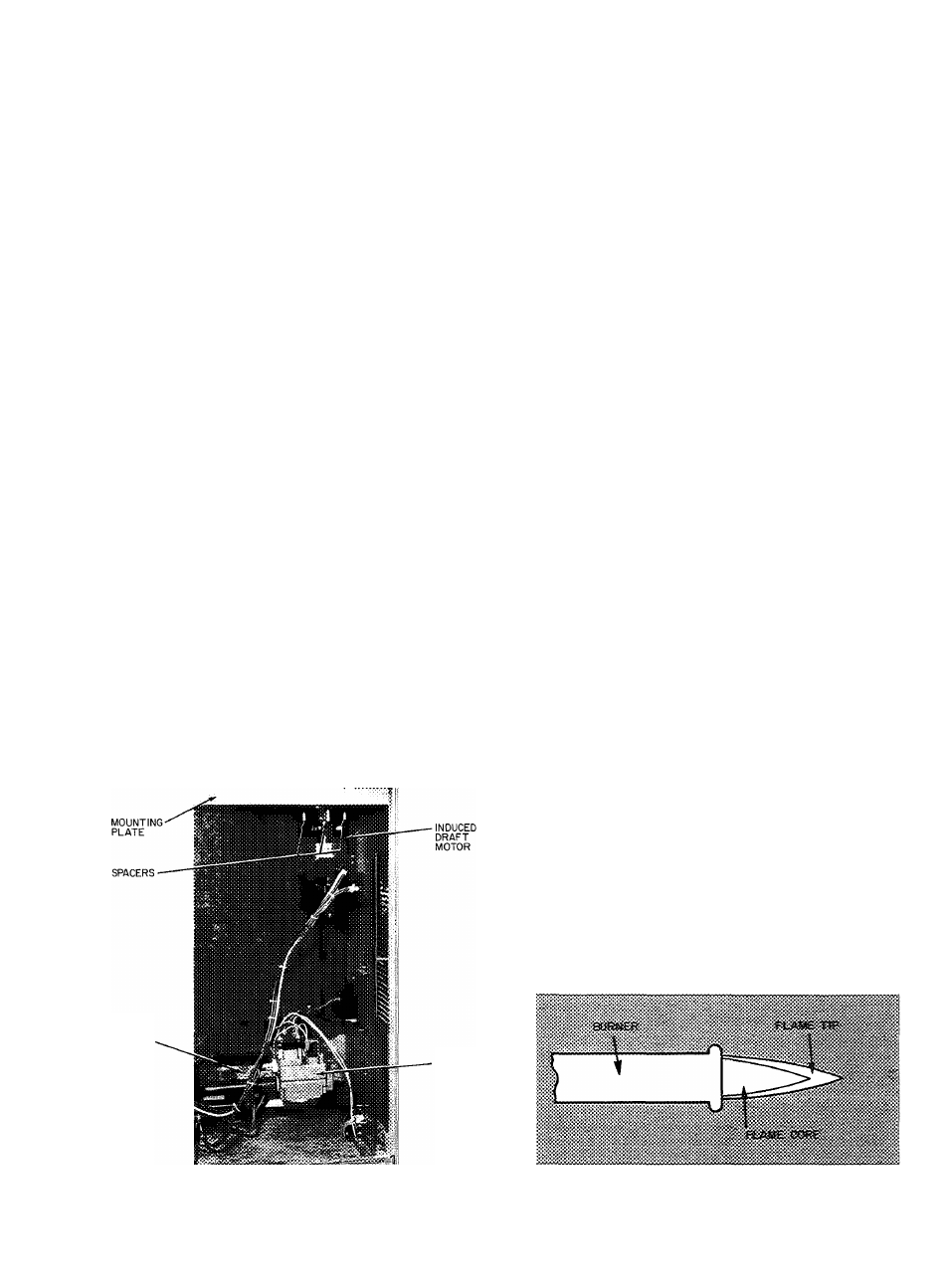
2. Remove the 6 screws that attach induced draft
motor mounting plate to blower housing
(Fig. 42). The mounting plate will drop down.
3. Remove the 4 wires attached to the motor and
remove assembly from unit.
4. To remove blower, remove setscrews.
5. To remove motor, remove blower, then remove
the nuts that hold motor to mounting plate.
NOTE; Do not lose spacers for induced draft
motor.
6. To reinstall, reverse the procedure outlined
above.
MAIN
BURNER
SECTION
MAIN
GAS
VALVE
Limit Switch — Aceess panel is located on the heat
section side panel (Fig. 3 and 4).
004,005,006,007 UNITS AND 48HDD,LDD/HD,
LD008 UNITS — Limit switch is located in the
upper section of the heat exchangers. Bi-metal
sensor is facing the airstream. Remove bracket
holding limit switch and remove screw holding
switch.
48HHD,LHD/HH,LH008 UNITS ^ Limit switch
is located on partition between blower section and
heat section. Remove plate and screw holding
switch.
Pilot Light — If pilot does not light as described in
Start-Up, Heating: Be sure pilot orifice is not
obstructed, gas pressure is not less than 3in. wg;
and air has been bled from gas supply. Check for
spark ignitor malfunctions as follows:
1. Shut off unit power supply.
2. Check that spark gap is 1/8 to 3/16 inch.
3. Check that spark generator is securely grounded
to furnace vestibule plate.
4. Check that high-voltage lead is securely con
nected between generator and electrode body.
5. Restore power. Check that 24 volts is supplied to
primary side of generator.
6. Check unit label diagram for correct terminal
usage if any wires are removed.
Automatic Pilot Adjustment
1. Turn off unit power supply, set system selector
switch at HEAT, and adjust thermostat to call
for heat.
2. Remove burner compartment access panel.
3. Remove screw cap cover on the top of the main
gas valve to expose pilot adjusting screw.
4. With a small screwdriver, turn adjustment screw
until flame is approximately 1 to 1-1/2 in. high.
5. Replace screw cap cover on pilot gas valve.
6. Observe burner operation and adjust main gas
valve for correct burner operation as required.
See Fig. 43 for proper flame appearance.
7. Replace all panels.
Automatic Gas Valve Sequence of Operation
— Thermostat calls for heat, energizing the spark
ignitor and simultaneously opening the pickup and
hold solenoids of the pilot gas valve (inside main gas
valve). The pilot gas ignites within 2 seconds, stop
ping the ignitor. Within 11 seconds, the pilot contact
(normally closed) opens, drops out the pickup sole
noid. Within 35 seconds, the pilot contact (normally
Fig. 42 — Burner Section Details
Fig. 43 — Proper Flame Appearance
21