Step 8 — make outdoor air inlet adjust, Ments and install outdoor air hood – Carrier 48HDT User Manual
Page 10
Attention! The text in this document has been recognized automatically. To view the original document, you can use the "Original mode".
THERMOSTAT
Factory Wiring
--------- Field Wiring
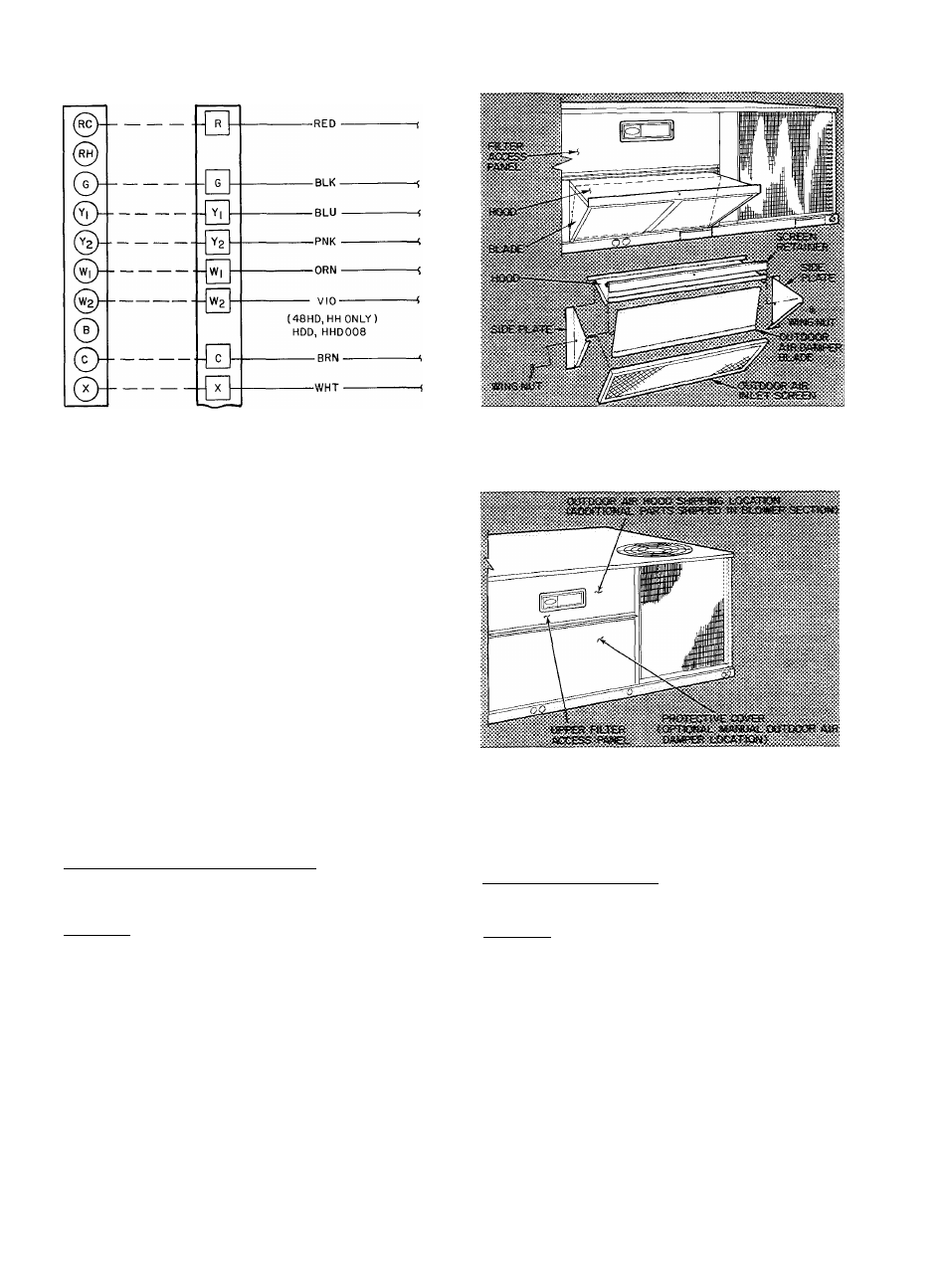
Fig. 8 — Control Wiring Connections
Route thermostat cable or equivalent single leads
of colored wire from subbase terminals through con
nector on unit to low-voltage connections as shown
in Fig. 8.
NOTE: For wire runs up to 50ft, use no. 18 AWG
insulated wire (35 C mininum). For 50 to 75 ft, use
no. 16 AWG insulated wire (35 C minimum).
Pass the control wires through the hole provided
in the corner post; then feed wires through the race
way built into the corner post to the 24-v barrier
located on the left side of the control box.
HEAT ANTICIPATOR SETTINGS — Set heat
anticipator settings at 1.20 for 460-voIt units and
1.00 for 208/ 230-volt units. Settings may be changed
slightly to provide a greater degree of comfort for a
particular installation.
Step 8 — Make Outdoor Air Inlet Adjustments
and Install Outdoor Air Hood
OPTIONAL OUTDOOR AIR DAMPER
48HDT,LDT004,005,006 and HD007 — Optional
outdoor air damper is shipped with hood broken
down inside of unit. See Fig. 9.
Assembly
1. Remove filter access panel.
2. Remove sheet metal parts from filter area.
3. Using screws provided, a.s.semble sides to the
inside of the hood. See Fig. 9.
4. Discard baffle.
5. Install damper blade by inserting threaded pins
through hole in side plates.
6. Use wing nuts provided to hold blade in place.
7. Install outdoor air hood assembly, using screws
provided.
8. Install outdoor air inlet screen and screen
retainer.
9. Replace access panel.
Fig. 9 — Outdoor Air Damper and Hood
Installation and Details
(004,005,006.007 Units)
Fig. 10 — Access Panel Location
(008 Units)
lO. Loosen wing nut on side plate to adjust blade.
Adjust damper blade to desired setting for out
side air intake.
48HD,LD/ HDD,LDD008 — Optional outdoor air
damper is shipped with hood broken down in unit
filter section. See Fig. lO.
Assembly
1. Remove protective cover from unit. See Fig. lO.
2. Remove upper filter aecess panel (save screws).
See Fig. lO.
3. Remove hood parts from unit evaporator fan
and filter area. Assemble hood top and side
plates as shown in Fig. 11. Do
n ot attach h ood
to u n it at th is tim e.
4. Adjust outdoor air damper blade to desired
setting for outside air intake by releasing linkage
rod setscrew and adjusting linkage rod. See
Fig. 12. Secure damper blade in desired position
with setscrew.
5. Remove screws holding manual outdoor air
damper to unit. See Fig. 13.
lO