Carrier 48HDT User Manual
Page 12
Attention! The text in this document has been recognized automatically. To view the original document, you can use the "Original mode".
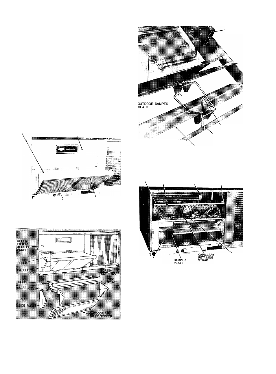
4. Remove mixed air thermostat (MAT.) capillary
retaining strap and stretch capillary through
notch in filter support. See Fig. 19. Route
through hook on upper left side of indoor coil
and secure end of capillary to retainer on lower
right side of indoor coil.
5. Fasten baffle to left side of damper plate with
round head screws provided. See Fig. 19.
6. Set vent position of damper by turning base unit
power on and allowing only the indoor fan to
run. Adjustment is made on left side of damper
motor by loosening vent position setscrew and
moving vent position lever back towards indoor
coil to CLOSE DAMPER or forward to OPEN
DAMPER. Once adjustment is made, retighten
setscrew and turn indoor fan off.
HOOD
UPPER FILTER
ACCESS PANEL
OUTDOOR AIR
INLET SCREEN
AIR SCREEN
RETAINER
Fig. 16 — Removing Economizer Upper Filter
Access Panel (004,005,006,007 Units)
Fig. 17 — Economizer Hood Installation
and Details (004,005,006,007 Units)
ACTUATOR
MOTOR
LINKAGE ROD
RETAINING STRAP
INDOOR DAMPER BLADE
Fig. 18 — Removing Indoor Blade Linkage
Retaining Strap (004,005,006,007 Units)
DAMPER
FILTER
MOTOR
SUPPORT
NOTCH
BASE UNIT
RECEPTACLE
• BAROMETRIC
RELIEF DAMPER
MIXED AIR
THERMOSTAT
CAPILLARY
Fig. 19 — Economizer
(004,005,006,007 Units)
7. Remove 4 screws holding economizer to unit.
Use screws to fasten hood to front of econo
mizer section.
8. Remove tape from outdoor air thermostat
(OAT.) and cooling lockout switch (CLS), and
fasten to inside of the hood with screws and
speed clips provided. See Fig. 20. Place knob,
12