Carrier 48HDT User Manual
Page 14
Attention! The text in this document has been recognized automatically. To view the original document, you can use the "Original mode".
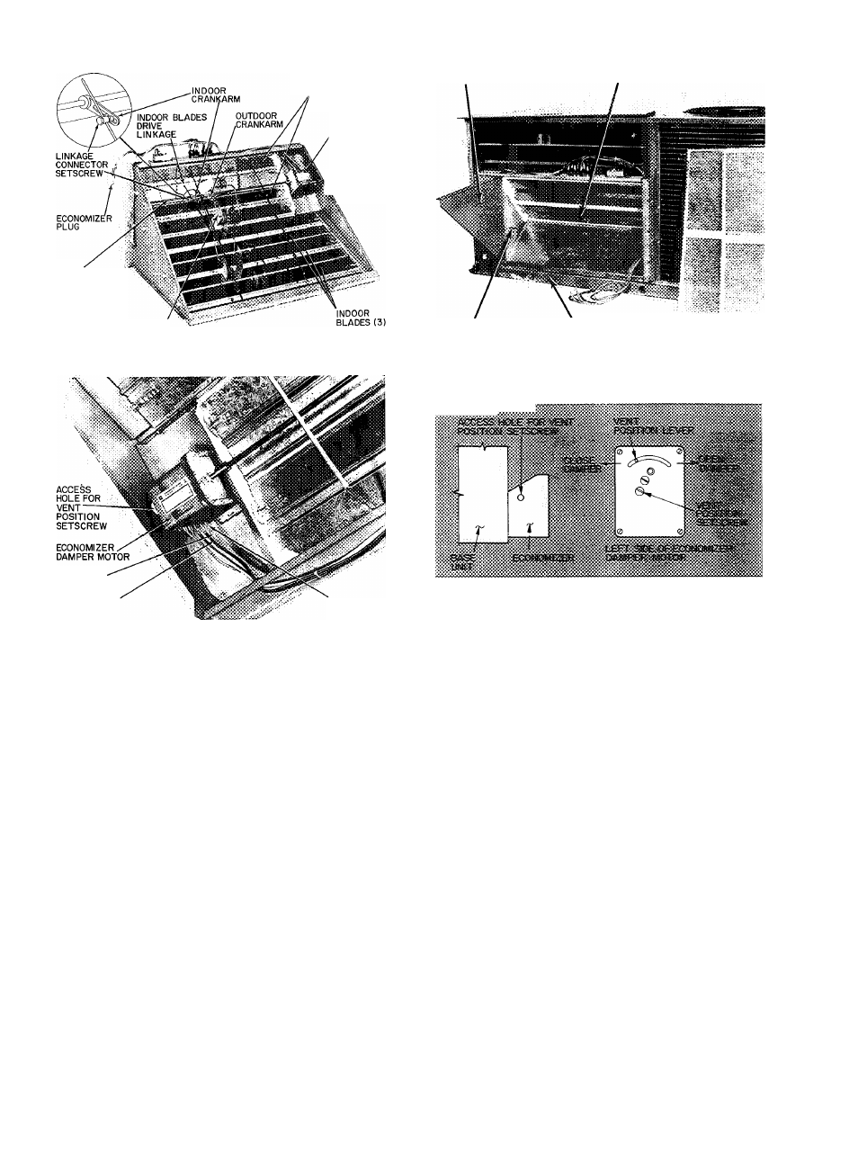
OUTDOOR BLADES (2)
MOTOR
ACCESS
HOLE
^FOR VENT
¡^POSITION
i SETSCREW
BAFFLE
ECONOMIZER ASSEMBLY
DRIVE
SHAFT
OUTDOOR DRIVE LINKAGE
Fig. 24 — Economizer Details (008 Units)
PINK WIRE
VIOLET WIRE
TERMINAL D
Fig. 25 — Economizer Motor Connections
(008 Units)
DAMPER PLATE
BASE RAIL
Fig. 26 — Baffle Installation Details
(008 Units)
...............iiSiSKiSSi
Fig. 27 ~ Vent Position Setting Details
(008 Units)
#
4. Determine if vent air is required in building to
be conditioned. If so, check for percentage of
vent air needed and record quantity for vent
adjustment in step 11.
5. Remove jumper plug from base unit receptacle
and discard. Insert economizer plug into recep-
. tacle. See Fig. 23.
Steps 6 through 8 involve releasing and adjust
ing indoor damper blades from factory set
position.
6. Release indoor blades drive linkage by loosen
ing linkage connector setscrew at indoor crank-
arm on drive shaft. See Fig. 24.
Remove pink wire from economizer damper
motor terminal D and temporarily tape bare
wire end.
Remove violet wire from economizer damper
motor and connect to terminal D on economizer
damper motor. See Fig. 25.
7. Jumper red (base unit 24-v power) and black
wires in 24-volt control box compartment. See
Fig. 10 and 12.
Turn on base unit power to energize evaporator
fan. The economizer’s outdoor blades should
open completely.
8. Adjust the indoor blades drive linkage so that
indoor blades are fully closed. Tighten the
linkage connector setscrew. Turn off base unit
power. Reconnect pink and violet wires to
economizer motor, as shown in Fig. 25.
9. If vent air is required, leave red and black wires
jumpered. If vent air is not needed, remove
jumper between red and black wires.
10. Fasten baffle to left side of damper plate with
round head screws provided. See Fig. 26.
11. If vent air is not required, go on to step 12. If
vent air is required, proceed as follows:
a.
b.
Turn on base unit power. This energizes the
evaporator fan motor.
Slide economizer out of unit so that access
hole to vent position setscrew is visible. See
Fig. 27.
14