Carrier 48HDT User Manual
Page 13
Attention! The text in this document has been recognized automatically. To view the original document, you can use the "Original mode".
supplied with accessory, on OAT. and set for 3 F
below indoor room thermostat setting.
If accessory enthalpy control is used in lieu of
OAT., refer to instructions shipped with
accessory.
9. Place outdoor air inlet screen in hood and
secure with retaining bracket across hood front.
See Fig. 16.
10. Replace upper filter access panel with screws
saved from step 1.
#
#
POWER FAILURE — Dampers have a spring
return. In event of power failure, dampers close
until power is restored. Do not manually operate
damper motor.
48HD,LD/ HDD,LDD008 — Optional economizer
is shipped with hood broken down in unit filter
section. See Fig. 21.
SPEED CLIPS
COOLING
LOCKOUT
SWITCH
(CLS)
OUTDOOR AIR THERMOSTAT
OR ENTHALPY CONTROL
OUTDOOR AIR HOOD SIDE PLATE
Fig. 20 — Enthalpy Control Position
(004,005,006,007 Units)
Fig. 21 — Access Panel Location
(008 Units)
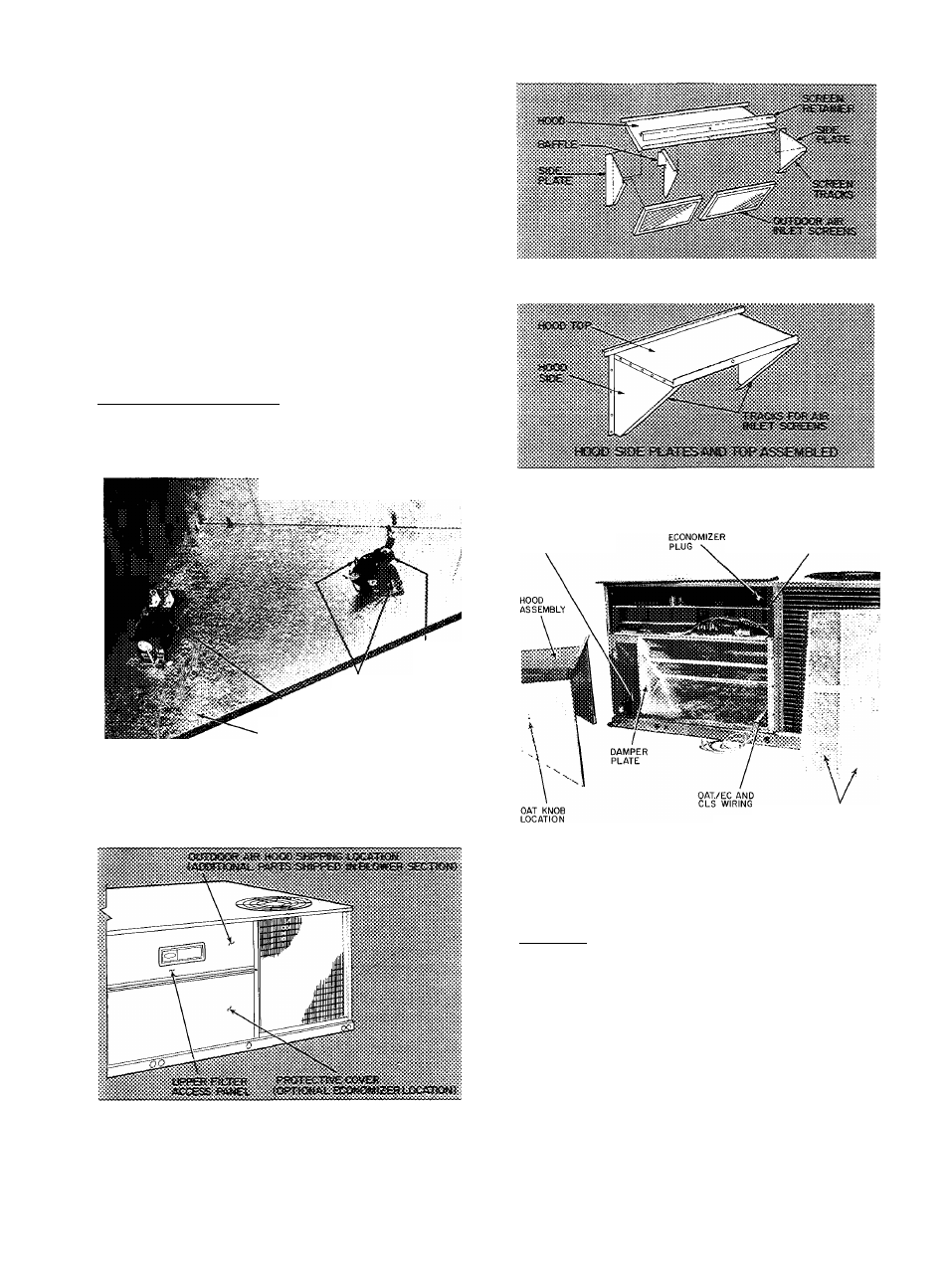
Fig. 22 — Outdoor Air Hood Details
(008 Units)
BAROMETRIC
RELIEF
DAMPER LOCATION
BASE UNIT
RECEPTACLE
OUTDOOR AIR
INLET SCREENS (2)
CLS — Cooling Lockout Switch
EC — Enthalpy Control
OAT — Outdoor Air Thermostat
Fig. 23 — Economizer Installed in Unit
(008 Units)
Assembly
1. Remove protective cover from unit. See Fig. 21.
2. Remove upper filter access panel (save screws).
See Fig. 21.
3. Remove hood parts from unit evaporator fan
and filter area. Assemble hood top and side
plates as shown in Fig. 22. Remove tape from
barometric relief damper (see Fig. 23).
D o n ot
attach h ood to u n it at th is tim e.
Put aside
baffle, screen retainer and retainer screw for
later assembly.
13