Outdoor air hood details (008 units), Fig. 12 — damper blade adjustment (008 units), N> <ì3 – Carrier 48HDT User Manual
Page 11: Viol, Fig. 15 — control box details (008 units)
Attention! The text in this document has been recognized automatically. To view the original document, you can use the "Original mode".
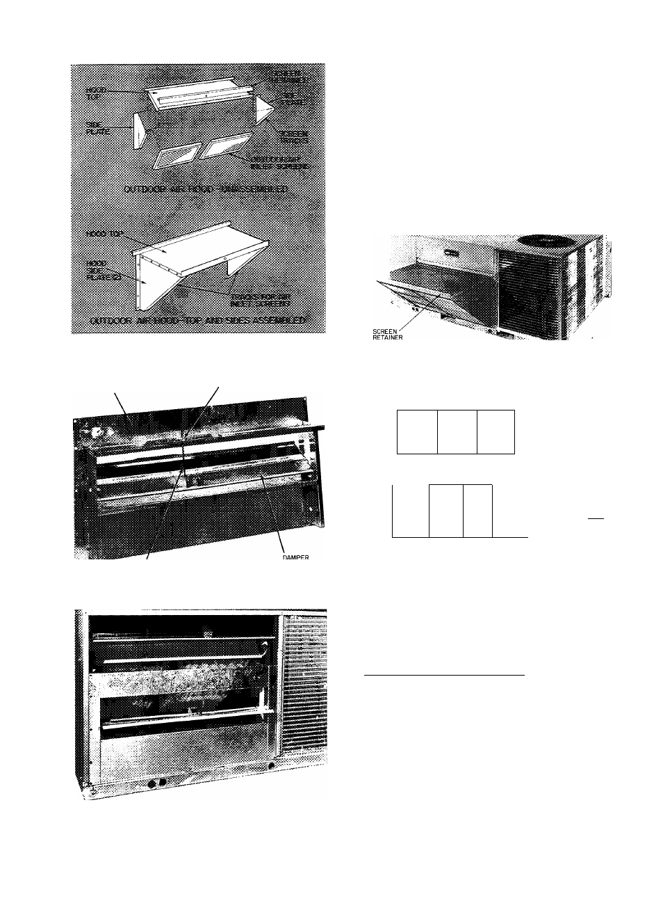
Fig. 11
Outdoor Air Hood Details
(008 Units)
MANUAL OUTDOOR
AIR DAMPER ASSEMBLY
LINKAGE
ROD SETSCREW
!»>•■
LINKAGE ROD
BLADE
Fig. 12 — Damper Blade Adjustment
(008 Units)
Fig. 13 — Manual Outdoor Air Damper
(008 Units)
7.
Install outdoor air hood assembly, using screws
from step 5. These screws secure the manual
outdoor air damper assembly and the outdoor
air hood to unit. See Fig. 13.
Slide outdoor air inlet screens into screen tracks
on hood side plates. While holding screens in
place, fasten screen retainer to hood using screw
provided. Make sure bottom edge of screens rest
inside base rail as shown in Fig. 14.
Replace upper access panel with screws saved
from step 2.
Fig. 14 — Outdoor Air Hood Installed
(008 Units)
0
0
0
0
0
0
0
0
m
TBI
<2> ®
(D ®
<2> ®
o@o
(rXjF^
® <§>
®
©•
TRAN^
^ '0*
XCLO
(D
□
6RN/YEL
1
1__
(D
EQUIPMENT
GROUND
FUSE-
a
Viol
C — Contactor Compressor
CLO — Compressor Lockout
IDR — Induced Draft Relay
IFC — Indoor Fan Contactor
LEGEND
IFR — Indoor Fan Relay
TB — Terminal Block
TDR — Time-Delay Relay
TRAN — Transformer
Fig. 15 — Control Box Details
(008 Units)
OPTIONAL ECONOMIZER
48HDT,LDT004.005.006/ HD007
1. Remove upper filter access panel (save screws).
See Fig.
\b.
2. Remove economizer hood parts from unit filter
area, and assemble leaving out the damper
blade. See Fig. 17. Remove tape from baro
metric relief damper.
3. Remove indoor blade linkage retaining strap
(Fig. 18). Place washer on linkage rod supplied
with accessory. Place linkage rod into hole “B”
of outdoor damper blade. Secure rod with blue
retaining clip provided.
11