Step' 9 — adjust evaporator fan speed — on, Step 9 — adjust, Evaporator fan speed – Carrier 48HDT User Manual
Page 16
Attention! The text in this document has been recognized automatically. To view the original document, you can use the "Original mode".
PINK
RED
CLS
EC
SEE NOTE
¡—0O^t5(3>-
!
^ OAT „
PINK
BLUE ■
CLS
— Cooling Lockout Switch
EC
— Enthalpy Control
OAT.
— Outdoor Air Thermostat
NOTE: When enthalpy control (EC) is installed, outdoor air thermo
stat (OAT ) is removed from economizer
Fig. 30 — Wiring Connections for Outdoor Air
Thermostat/or Enthalpy Control and
Cooling Lockout Switch (008 Units)
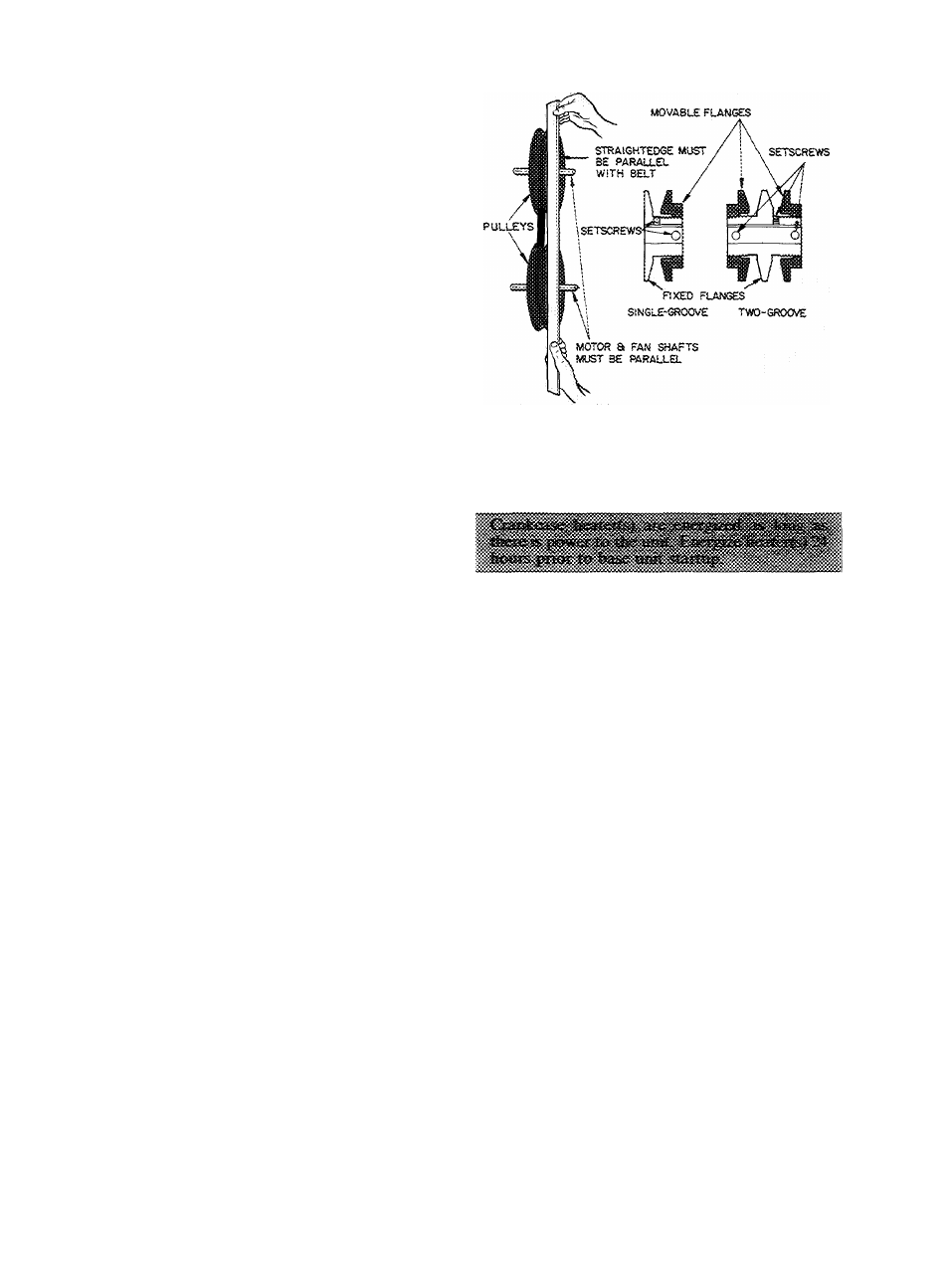
Fig. 31 — Indoor Air Fan Pulley Adjustment
Step' 9 — Adjust Evaporator Fan Speed — On
48HDT,LDT004,005,006 and 48LH006 units, the
evaporator fan motor factory speed setting is shown
on label diagram affixed to base unit. If other than
faetory setting is desired, refer to label diagram for
motor reconnection.
On 48H H006 and all 007 and 008 units, fan motor
pulleys are factory set for speed shown in Table 1.
To change fan speeds:
1. Shut off unit power supply.
2. Loosen belt by loosening fan motor mounting
plate nuts.
3. Loosen movable pulley flange setscrew (see
Fig. 31).
4. Screw movable flange toward fixed flange to in
crease speed and away from fixed flange to
decrease speed. Increasing fan speed increases
load on motor. Do not exceed maximum speed
specified in Table 1.
5. Set movable flange at nearest key way of pulley
hub and tighten setscrew. (See Table 1 for speed
change for each full turn of pulley flange.)
To align fan and motor pulleys, loosen fan pulley
setscrews and slide fan pulley along fan shaft. Make
angular alignment by loosening motor from mount
ing plate.
To Adjust Belt Tension — Loosen fan motor pivot
bolts. Move motor mounting plate up or down for
proper belt tension (1/2-in. deflection with one
finger) and tighten pivot bolts. Adjust lock bolt and
nut on mounting plate to secure in fixed position.
START-UP
Unit Preparation — Make sure that unit has been
installed in accordance with installation instructions
and applicable codes.
Return Air Filters — Make sure correct filters are
installed in filter tracks. See Table 1. Do not operate
unit without return air filters.
Outdoor Air Inlet Screens — Outdoor air inlet
screen(s) must be in place before operating unit.
Compressor Mounting — Compressors are inter
nally spring mounted. Do not loosen or remove
compressor holddown bolts.
Internal Wiring — Check all electrical connections
in unit control boxes. Tighten as required.
Refrigerant Service Valves — Each unit system
has 2 Schrader type service ports, one on the suction
line and one on the compressor discharge line. Be
sure that caps on the ports are tight.
Cooling — To start unit, turn on main power
supply. Set system selector switch at COOL and
fan switch at AUTO. Adjust thermostat to a setting
below room temperature. Compressor starts on
closure of contactor.
Check cooling effects at a setting above room
temperature. Check unit charge. Refer to Refrig
erant Charge in Service section.
Reset thermostat at a position above room tem
perature. Compressor will shut off.
TO SHUT OFF UNIT — Set system selector switch
at OFF position or reset thermostat at a position
above room temperature. Units are equipped with
Signal-LOC™ protection device. Unit shuts down on
#
L
16