Iismm – Carrier 48HDT User Manual
Page 15
Attention! The text in this document has been recognized automatically. To view the original document, you can use the "Original mode".
- "
■■ 'OUTDOOR AIR V
h
ERMOSTAT
'
(TERMINALS ARE UP)
i l : T E R M I N A L S :;i-:;Sv
T T y T , ; ' ............
&s;i®
COOLING
lockout
.................................i SWITCH
iismM
HOOD
ACCESSORY
•v\ ENTHALPY
.
! CONTROL\
I
CONTROL
>:¥
COOLING
LOCKOUT
v‘ X'^ SWITCH
HOOD
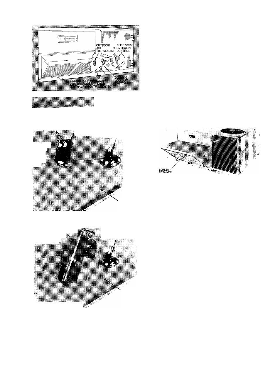
Fig. 28 — Outdoor Air Thermostat/Enthalpy
Control and Cooling Lockout Switch
Installation (008 Units)
c. Adjust vent opening by loosening vent posi
tion setscrew on left side of economizer
damper motor and setting vent position
lever to adjust damper (see Fig. 27). Move
vent position lever back toward evaporator
coil to close damper or forward to open
damper. When adjustment is completed,
retighten setscrew.
d. Turn off base unit powerand removejumper
from red and black wires.
e. Slide economizer assembly back into unit.
12. Remove tape from outdoor air thermostat
(OAT.) and cooling lockout switch (CLS), and
fasten to inside of hood with screws and speed
clips provided. Make sure terminals on OAT.
are up. See Fig. 28.
Fig. 29 — Economizer and Outdoor Air Hood
Assembled to Unit (008 Units)
13. Fasten hood top and side plate assembly
(Fig. 29) and economizer to unit with screws
supplied. Before attaching, make sure bottom
of hood assembly is resting on top of unit base
rail.
14. Place knob supplied with accessory economizer
on OAT. See Fig. 28. Set for 3 degrees below
indoor room thermostat setting.
If accessory enthalpy control (EC) (Fig. 28) is
used in lieu of OAT., refer to instructions
shipped with accessory enthalpy control .for
installation and adjustment.
15. Connect OAT./EC and CLS per unit label.
See Fig. 30.
Connect 2 economizer wires to each switch
with quick-connects. Unit connecting wires are
shipped taped on outdoor blade. See Fig. 23.
16. Slide outdoor air inlet screens in hood screen
tracks. Secure screens with screen retainer
across hood front. Secure screen retainer with
screw provided. See Fig. 29.
17. Replace upper filter access panel with screws
saved from step 2.
18. Turn base unit power on.
15