Service notes, Valve when, Rumnwg – Carrier 06E User Manual
Page 8
Attention! The text in this document has been recognized automatically. To view the original document, you can use the "Original mode".
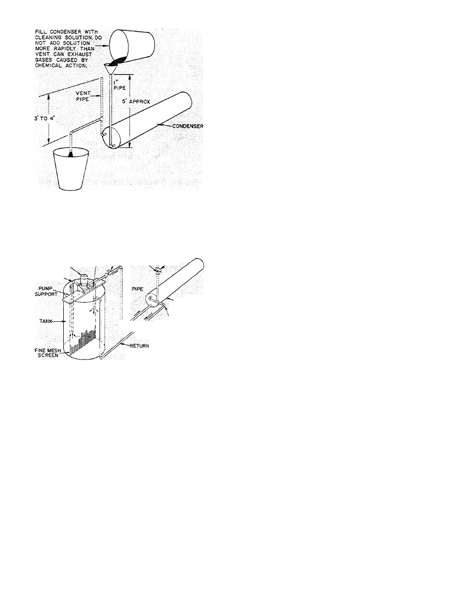
Fig. 10 — Gravity Circulation
ceOTarcGAt.
pcwp
sas
vemt
-
30 OPM AT 35' HEAD
PRl«WS /VAl.VE£\..
PUMP. • "
^
SUCT:ON
: ClXSt VENT PIPE
;
VALVE WHEN
; PUMP IS
:
RUMNWG
COiv-CEAiSES
,
REMCA'E WATER
^
REGULATINC-
valve
Fig. 11 — Forced Circulation
REMOVING, INSPECTING AND
REPLACING COMPONENTS (Fig. 12)
Service Notes
1. All compressors have interchangeable valve
plate assemblies, unloader valves and oil pump
bearing head assemblies. For replacement items
use Carrier Specified Parts.
2. Before compressor is opened, the refrigerant
must be removed from it by the Pumpdown
method.
Start compressor, close suction shutoff
valve, and reduce crankcase pressure to 2
psig. (Jumper low pressurestat.)
Stop compressor and isolate from system by
closing discharge shutoff valve.
Bleed any residual refrigerant. Drain oil if
necessary.
3. After disassembly, clean all parts with solvent.
Use mineral spirits, white gasoline or naptha.
a.
c.
4.
5.
Before assembly, coat all parts with compressor
oil and clean and inspect all gasket surfaces.
Replace all gaskets with new factory-made
gaskets. See Table 4 for torque values.
After reassembly, evacuate compressor and
open suction and discharge valves. Restart
compressor and adjust refrigerant charge.
Legend (Fig. 12)
1 -
Compressor Motor —
29
-
Bottom Cover Plate
Stator and Rotor
30
—
Pump End Bearing
2 -
Motor Key
Head Package
3 -
Rotor Plate Washer
31
-
Pump Rotor
4 -
Rotor Lock Washer
32
-
Pump Vane
5 -
Rotor Lock Bolt
33
Pump Vane Spring
6
—
Motor Lock Bushing
34
-
Pump Vane Spring
7 _
Roll Pin
Guide
8
_
Acorn Nut and Gasket
35
“
Retaining Spring
Ring Spacer
36
_
Oil Feed Guide Vane
9 —
10
Junction Box
37
-
Oil Feed Guide Vane
Spring
11 — Terminal Plate Assembly
38
_
Oil Pump Drive Segment
12 — Terminal Bolt Assembly
39
_
Screw, Soc Head
13 -
Terminal Bolt Assembly
1/4 - 28
X
5/8 in
14 -
Cover Plate
40
_
Screw, Soc Head no 10
15
Hex Head Screw
- 32
X
1/2 in
16 -
Cylinder Head Bolts
41
-
Cover Plate
17
—
Connecting Rod and
42
-
Cover Plate Cap Screw
Piston Assemblies
43
Oil Relief Piston
18 -
Compressor Crankcase
44
-
Crankshaft
19 -
Motor End Cover
45
_
Bearing Washer
20
-
Cylinder Head —
46
_
Piston Ring (Oil and
Center Bank
Compression)
21
-
Cylinder Head — Capacity
47
__ Piston, Piston Pin and
Control Side Bank
Retaining Ring
22
-
Internal Relief Valve
Package
23
_
Crankcase Oil Filter
48
-
Connecting Rod and
Screen
Cap Assembly
24
-
Oil Sight Glass Assembly
49
-
Valve Plate Package
25 -
Oil Sight Glass 0-Ring
50
-
Valve Plate
Gasket
51
-
Discharge Valve Stop
26
-
Oil Sight Glass Screw
52
-
Discharge Valve
27
Oil Sight Glass Lock
53
_
Valve Stop Support
Washer
54
_
Cap Screw, Valve Stop
28
_
Pipe Plug Gasket
(hex head)
55
— Suction Valve