Compressor running gear removal, Compressor running gear replacement – Carrier 06E User Manual
Page 14
Attention! The text in this document has been recognized automatically. To view the original document, you can use the "Original mode".
REMOVE
1. Acorn nut and washer.
2. Back out locking pin and bushing.
REPLACE
1. Screw in locking pin bushing until it rests on
stator core.
2. Wrap a piece of tape around 3/8 in. drill bit,
2-1/16 in. from cutting edge.
3. Ream out bushing (3/8 in. drill) and drill into
stator core until tape is flush with top of
bushing. (Remove drill chips.) Back off locking
pin bushing 1/8 of a turn.
C A U T I O N '
B e f o r e
d r i l l i n g ,
b e
s u r e
s t a t o r
v e n t
h o l e s d o n o t l i n e u p w i t h l o c k i n g p i n h o l e . V e n t
h o l e s
a r e
d r i l l e d
h o r i z o n t a l l y
t h r u
s t a t o r ,
a n d
c a n b e s e e n f r o m e n d b e l l s i d e .
4. Tap locking pin into position. (Top of bushing
should be approximately 1/16 in. above top of
pin.)
5. Peen top of bushing over roll pin.
6. Replace washer and acorn nut.
COMPRESSOR RUNNING GEAR REMOVAL
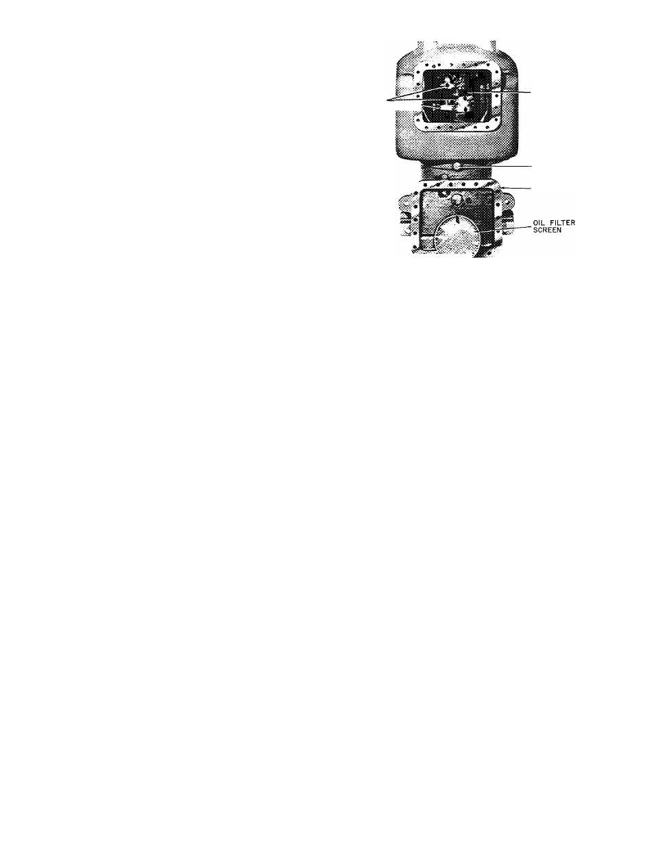
Connecting Rod and Piston Assembly
— Remove
cylinder heads, valve plate assemblies, crankcase
bottom cover plate, oil filter screen, and con
necting rod caps (Fig. 23.) (Label caps and rods so
they may be reinstalled in same place on crank
shaft.) Push connecting rod and piston assemblies
up thru cylinder deck. Disassemble connecting rods
from pistons by removing retaining rings and
piston pins. Remove oil and compression rings from
piston. (Keep each connecting rod and piston
assembly together for proper reassembly.) Check
all parts and crankpin journals for wear (refer to
Table 5 for wear limits).
Crankshaft
— Remove pump end bearing head and
rotor. If connecting rod and piston assemblies are
still in place, remove connecting rod caps and push
piston assembly up into cylinder for crankshaft
clearance. Pull crankshaft out thm pump end
opening. Inspect crankshaft journals for wear and
tolerances shown in Table 5. Check oil passages
and clean if clogged.
Pump End Main Bearing
is a machined part of the
oil pump and bearing head casting. Disassemble
bearing head. If bearing is scored or worn, replace
the complete bearing head.
Crankcase and Motor End Main Bearings
are not
field replaceable. If bearings are worn or damaged,
replace compressor.
CONNECTING
RODS a CAPS "'psTT;-
CRANKSHAFT
OIL DRAIN PLUG
(MAGNETIC)
BOTTOM COVER
PLATE
. 'Cv •
Fig. 23 — Removing Connecting Rod and
Piston Assemblies
COMPRESSOR RUNNING GEAR
REPLACEMENT
Crankshaft
— Be sure compressor end bearing
washer is in place on dowel pin. Install crankshaft
thru pump end, carefully guiding it thru main
bearings. Replace rotor.
Connecting Rod and Piston Assembly (Fig. 12) —
Attach connecting rods to pistons with piston pins,
and lock in place with retaining rings. Place
retaining rings with the gap on the side. They
should be tight enough so they cannot be rotated
by finger pressure.
RINGS
1. Check ring gap by inserting each ring separately
in cylinder approximately 3/8 in. from top.
Ring gap should be between .002 in. and
.007 in.
2. Install compression ring in top piston groove
with side marked “Top” toward piston head.
Install oil ring below compression ring with
notched end on bottom. Stagger ring gaps
around piston.
3. Measure side clearance between ring and piston
(Table 5). Check rings for free action.
Install connecting rod and piston assemblies
into cylinders. Place chamfered sides of connecting
rods against radius of the crankpins. Install
connecting rod caps to matching connecting rods
thru bottom cover plate. Be sure chamfered sides
of caps are against radius of crankpins. Caps are
locked in place with nylock cap screws. Use 8—10
Ib-ft torque to tighten cap screws.
Turn crankshaft to be sure there is no binding
between bearing surfaces and journals. Replace oil
screen, bottom cover plate, valve plates and
cylinder heads.
14