Lubrication system, Fig. 14 — pump end bearing head package – Carrier 06E User Manual
Page 10
Attention! The text in this document has been recognized automatically. To view the original document, you can use the "Original mode".
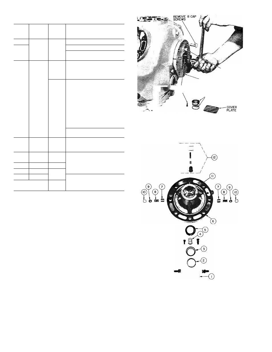
Table 4 — Torque Values
SIZE
DIAM
(in.)
THREADS
PER IN.
TORQUE
RANGE
(Ib-ft)
USAGE
Xe
27 (pipe)
8-12
Pipe Plug — Crankshaft
%
18
20-25
Pipe Plug — Crankcase
%
20
8-10
8-12
Conn. Rod Cap Screw
Junction Box
‘/4
28
3-5
14-18
14-18
14-18
Sight Glass
Oil Pump Drive Segment
Unloader Valve
Discharge Valve Stop
Xe
18 (pipe)
15-24
15-24
Cover Plate — Pump End
Bearing Head
Discharge Service Va!ve(4 cyl)
%
16
30-40
30-40
30-40
25-30
2-4
Bottom Plate — Crankcase
Compressor Foot
Terminal Block
Oil Plug — Pump End Bearing
Head
Terminal Bolts
%
18 (pipe)
30-40
Pipe Plug — Junction Box
Xa
14
55-65
55-65
Motor End Cover
Pump End Bearing Head
X
13
90-100
90-120
90-120
Cyl inder Head
Discharge Service Valve (6 cyl)
Suction Service Valve (4 cyl)
V,
11
90-120
90-120
Suction Service Valve (6 cyl)
Rotor Lock — Crankshaft
X
18
60-75
Oi 1 Drain Plug
X
16
105
Stator Lock
No. 6
32
1-2
Check Valve Body — Crankcase
No. 10
32
4-6
4-6
Oil Pump Drive Segment
Terminal Screw
LUBRICATION SYSTEM
Testing Oil Pump
— An oil pressure tap is located
above oil pump cover plate (Fig. 13). Oil pressure
should be 12—18 psi above suction pressure.
OIL FILTER SCREEN is accessible thru bottom
cover plate. Remove and inspect strainer for holes
and dirt. Clean it with solvent and replace.
Oil Pump and Bearing Head
— The oil pump
assembly is contained in the pump end bearing
head aluminum casting. (The pump end main
bearing is a machined part of this casting — no
insert bearing.)
REMOVE bearing head from crankcase and dis
assemble oil pump. Drive segment cap screws must
be removed before bearing head can be removed
(Fig. 13). Remove pump vane assemblies from
both sides of bearing head. Push the pump rotor
out of the bearing head by pushing against the
bearing side of the rotor. Check all parts (Fig. 14)
for wear and damage.
REPLACE
1. Install the rotor retaining ring in the ring groove
of the pump rotor with chamfered edge toward
compressor. Compress retaining ring, and insert
pump rotor into bearing head.
OIL
PRESSURE
TAP
^
drive
segment
CAP
screws
PUMP END
BEARING HEAD
OIL FEED GUIDE VANE
AND SPRING
Fig. 13 — Removing Pump End Bearing Head
1
— Cover Plate
2
— Oil Feed Guide Vane Spring
3
— Oil Feed Guide Vane
4
— Drive Segment
5
— Pump Rotor
6
— Pump End Bearing Head
7
— Pump Vane
8
— Pump Vane Spring
9
— Pump Vane Spring Guide
10
— Retaining Spring
11
— Pump End Main Bearing
12
— Oil Relief Piston
Fig. 14 — Pump End Bearing Head Package
10