Fig. 7 — capacity control valve – Carrier 06E User Manual
Page 6
Attention! The text in this document has been recognized automatically. To view the original document, you can use the "Original mode".
PRESSURE
DIFFERENTIAL
ADJUSTMENT SCREW
SEALING
BYPASS
CYLINDER
CAP
PISTON
HEAD
CONTROL SET
POINT ADJ NUT
POPPET VALVE'
BLEED ORIFICE'
DISCHARGE MANIFOLD
SUCTION PRESSURE
nZH DISCHARGE PRESSURE
DISCHARGE
SUCTION
VALVE
PISTON VALVE
UNLOADED OPERATION
BYPASS PASSAGE
COMMUNICATES
WITH
SUCTION MANIFOLD
-SUCTION MANIFOLD
l~~~1 DISCHARGE PRESSURE
LOADED OPERATION
Fig. 6 — Capacity Control Valve Operation
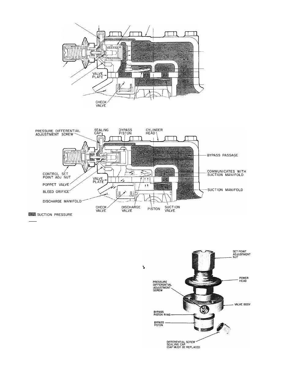
TO REGULATE CONTROL SET POINT (Refer to
Fig. 7) —Turn adjustment nut clockwise to its
bottom stop. In this position, set point is 85 psig.
Control set point is then regulated to desired
pressure by turning adjustment nut counterclock
wise. Each full turn decreases set point by 7.5 psig.
Approximately 11 1/2 turns counterclockwise will
decrease control set point to 0 psig. Table 3 shows
the steps of control.
PRESSURE
DIFFERENTIAL
ADJUSTMENT
(Fig. 7) — Turn differential adjusting screw counter
clockwise to its back-stop position. In this posi
tion, differential is 6 psi. Pressure differential is set
by turning adjustment screw clockwise. Each full
turn increases differential by 1.5 psi. Approxi
mately 10 turns clockwise will increase pressure
differential to 22 psi.
CONTROL
TO PREVENT REFRIGERANT LEAKAGE)
Fig. 7 — Capacity Control Valve