Fig. 5 — timer cycle protection devices, Capacity control system, Capacity control valve adjustments – Carrier 06E User Manual
Page 5
Attention! The text in this document has been recognized automatically. To view the original document, you can use the "Original mode".
Timer Functions
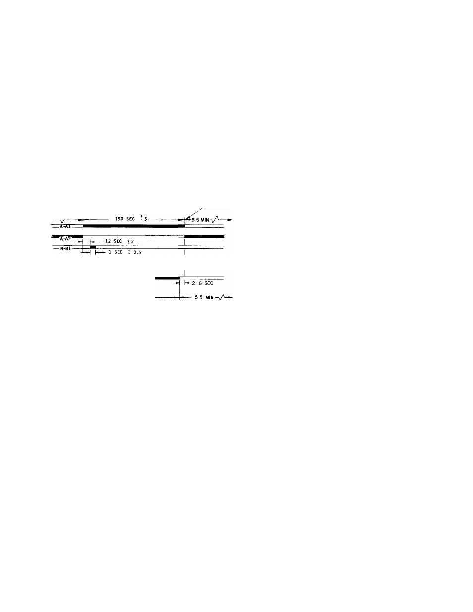
(See Fig. 5 — Tinier Cycle)
1. Switch A (contacts A-Al and A-A2) provides
Time Guard® function. Start of compressor is
delayed approximately 5.5 minutes after shut
off. The minimum time between starts of
compressor is 8 minutes.
2.
Switch B (contacts B1 and B—B2) starts
compressor and de-energizes the crankcase
heater. These contacts also provide one-second
time delay for part-winding start.
3. Switch E (contacts E—El) provides approxi
mately 40-second bypass of oil-pressure switch
(OPS) at start-up. Compressor will shut off if
sufficient oil pressure does not build up.
4. Switch D (contacts D—Dl) bypasses the low-
pressure switch (EPS) for 2.5 minutes at start
up for winter start control.
(BLACK DENOTES CLOSED CONTACTS)
0 MIN OR
8 MIN
TIMER POSITION DURING
UNIT OPERATION-
»TT?*
-'E-El-
-xA-
40 SEC +5
2-6 SEC
---
150 SEC
Fig. 5 — Timer Cycle
PROTECTION DEVICES
High-Pressure Switch
— Check by throttling con
denser water or blocking air flow on air-cooled
units, allowing head pressure to rise gradually.
Check discharge pressure constantly throughout
procedure. Compressor should shut off within 10
psi of values shown in Table 1.
Low-Pressure Switch
— Check by slowly closing
suction shutoff valve or by completely closing
liquid line shutoff valve. A decrease of suction
pressure will follow. Compressor should shut off
within 4 psi of values shown in Table 1.
Oil Pressure Switch
(OPS) protects against damage
from loss of oil and failure of pressure buildup
during start-up. Switch time delay (approximately
35 seconds) is derived from being properly wired
to the ambient and voltage insensitive Time Guard
timer. If OPS locks out unit,
d e t e r m i n e a n d c o r r e c t
t h e c a u s e
(such as loss of compressor oil or flooded
compressor)
b e f o r e
r e s t a r t i n g
u n i t
Restart by
pushing the control circuit switch on unit control
box to “Stop” then to “Reset.” Failure to correct
the cause of the OPS lockout will constitute abuse.
E q u i p m e n t f a i l u r e d u e t o a b u s e i s n o t c o v e r e d b y
t h e W a r r a n t y .
Time Guard Control
protects compressor against
short cycling. See Start Compressor.
Crankcase Heater
prevents absorption of liquid
refrigerant by oil in crankcase during brief or
extended shutdown periods. Source of 115-volt
power is the auxiliary control power, independent
of the main unit power. This assures compressor
protection even when main unit power disconnect
switch is off.
N e v e r o p e n a n y s w i t c h o r d i s c o n n e c t t h a t w i l l
d e - e n e r g i z e
t h e
c r a n k c a s e
h e a t e r
u n l e s s
u n i t
i s
b e i n g
s e r v i c e d
o r
i s
t o
b e
s h u t
d o w n
f o r
a
p r o l o n g e d p e r i o d A f t e r a p r o l o n g e d s h u t d o w n o r a
s e r v i c e
j o b ,
e n e r g i z e
t h e
c r a n k c a s e
h e a t e r
f o r
2 4
h o u r s b e f o r e s t a r t i n g t h e c o m p r e s s o r .
Compressor Motor Protection
consists of 3 tem
perature sensors embedded in motor windings and
connected to a solid state module in unit control
box.
When an overtemperature condition causes
module to shut compressor off, push control circuit
STOP switch. Investigate cause of compressor shut
down and correct. After compressor cools, push
control circuit START-RESET switch. Compressor
will restart after Time Guard delay period.
SOLID STATE MODULE is checked by applying
unit control voltage to terminals T1 and T2 (see
label diagram), then checking for continuity across
terminals Ml and M2. If no continuity between Ml
and M2, check temperature sensor resistance using
a volt-ohmmeter. If all sensors check below 95
ohms (180 F) and there is no continuity between
module terminals Ml and M2, replace module.
C A U T I O N : D o n o t
u s e a
b a t t e r y p o w e r e d t e s t
l a m p
t o
c h e c k
s e n s o r s
E x c e s s i v e
c u r r e n t
c a n
c a u s e d a m a g e
If one sensor fails, it can be jumpered out of
the circuit with a 75 ohm, or higher, resistor (rated
at 2 watts or higher) across the proper sensor
terminal and common terminal. If a short to
ground in sensor circuit is indicated, replace
compressor motor.
CAPACITY CONTROL SYSTEM
Capacity Control Valve(s)
is controlled by suction
pressure and actuated by discharge pressure. Each
valve controls 2 cylinders. On start-up, controlled
cylinders do not load up until differential between
suction and discharge pressure is 10 psi (see Fig. 6).
D o
n o t
u s e
a u t o m a t i c
p u m p d o w n
c o n t r o l
o n
0 6 E , 0 7 E u n i t s e q u i p p e d w i t h u n l o a d e r v a l v e s . U s e
s i n g l e
p u m p o u t
o r
s o l e n o i d
d r o p
( m i n i m u m
p r o
t e c t i o n ) c o n t r o l
Capacity Control Valve Adjustments
CONTROL SET POINT (cylinder load point) is
adjustable from 0 psig to 85 psig. Pressure differ
ential between cylinder load-up point and cylinder
unload point is adjustable from 6 psi to 22 psi.