Fig. 3 — 07e water-cooled condensing units, Iva“' iv, 4~vvu 2v – Carrier 06E User Manual
Page 2
Attention! The text in this document has been recognized automatically. To view the original document, you can use the "Original mode".
M ODF*
DISCHARGE VALVE
(MAY BE ROTATED 180°
DIAM KNOCKOUT
L ODF
SUCTION VALVE
(MAY BE ROTATED 360°
AT 90° INTERVALS)
2-31| OVERALL HEIGHT
'A~
OVERALL
LENGTH
(INCLUDES
CONTROL BOX
OVERHANG)
DIAM-4 HOLES
*1 nstall pressure relief device in discharge line
Pressure relief setting is 465 psig
tOverall width includes projection of fuse
holders
06E Hermetic Compressor Unit Dimensions
UNIT 06E
mMENMONS
A
CONNECT T
ons
On ) u
M
V022
3-1 1 %
IV«
W027
3-1IV«
iVa“'
IV,
4~VVu
2v; '
iVa
JW0j44_
" 2Va ”■
1 Vs
Fig. 2 —06E Hermetic Compressor Units
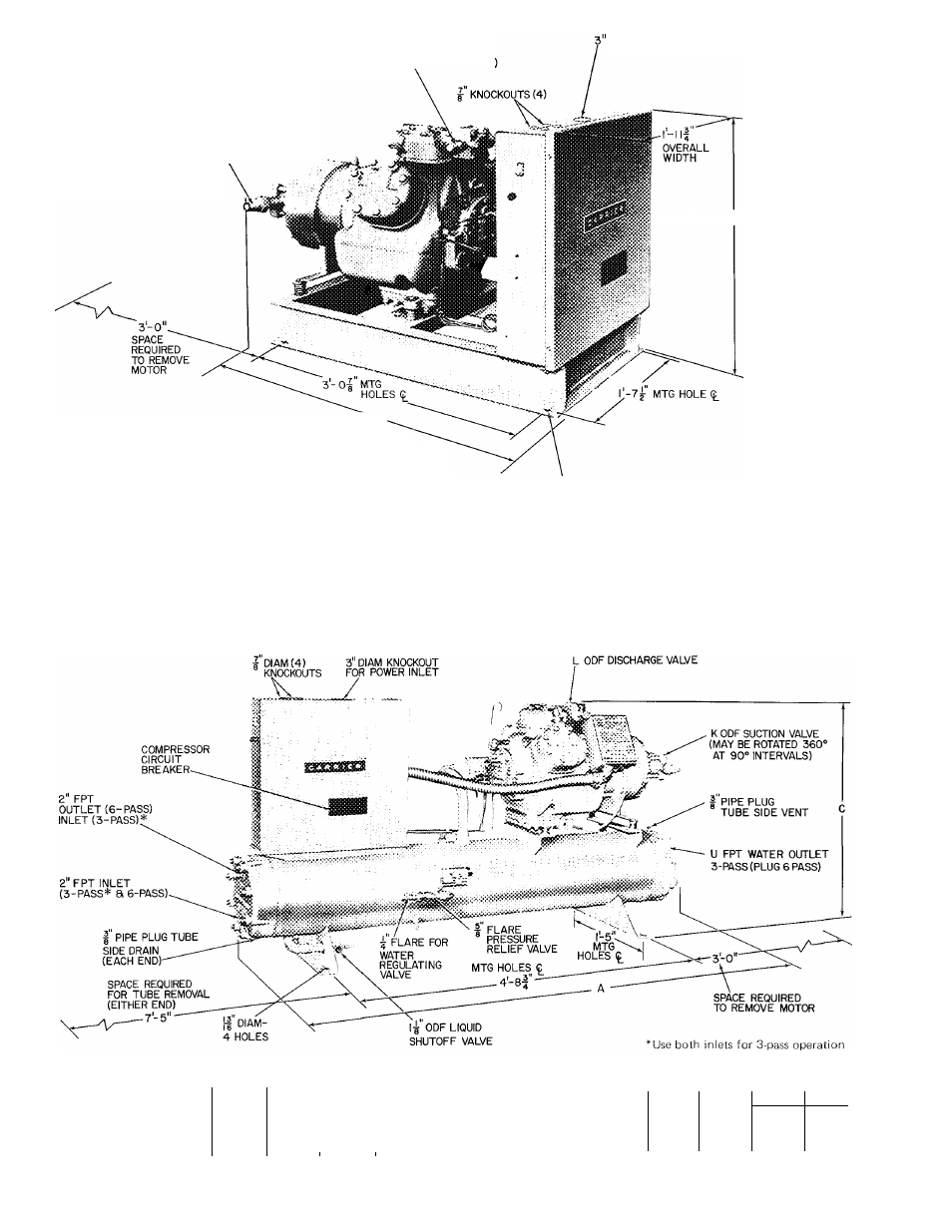
UNIT 07E
DIMENSIONS (fi
Overall Width
A022
§027
§033
A
6- 5
6- 5
6- 5
C
2-1 IV
3- 0
2-1 1V2
l-nVs
1 -1 1V
1-1IV
07E Water-Cooled Condensing Unit Dimensions
0044
_UNJT 07E^
6-7V
CONNECTIONS (ii
3-2 Vs
2-3 Vs
A022
B027
B033
0044
K
iVs
IVs
2Vs
2Vs
L
iVs
IV«
IVs
iVs
U
2V
2V
2V
3
Fig. 3 — 07E Water-Cooled Condensing Units
HR
Certified dimension drawings available on request.