Fig. 20 — removing stator, Fig. 22 — stator locking assembly – Carrier 06E User Manual
Page 13
Attention! The text in this document has been recognized automatically. To view the original document, you can use the "Original mode".
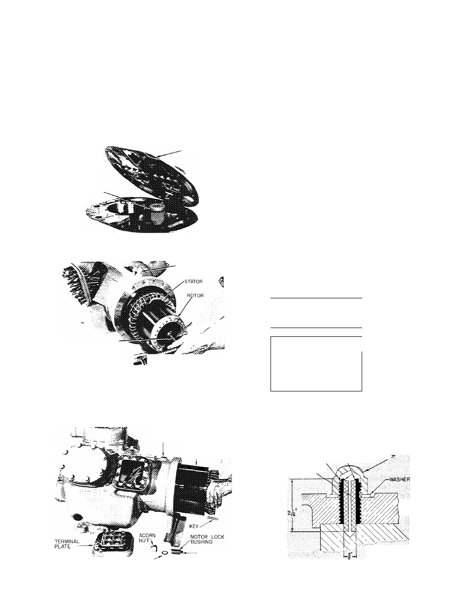
Stator
is a slip fit in motor housing. It is held in
place by both an axial key and a locking assembly
consisting of an acorn nut, locking pin, motor lock
bushing and a washer. Remove acorn nut and
washer. Back out locking pin and bushing. With
draw stator (Fig. 20). Axial key positions stator
and crankcase. If necessary, heat crankcase motor
housing (not over 20 to 30 F above stator temp).
Check stator for damage to windings and lead
wires. Use a megohmmeter to check for grounds or
shorts between windings.
RUBBER PLUG
VALVE PLATE
STATOR LOCKING
ASSEMBLY
JACKSCREW
^OTOR LOCK BOLT
Fig. 19 — Removing Rotor
MOTOR REPLACEMENT
Stator and Rotor
— Install stator halfway into
housing. Insert the terminal leads first, guiding
them to terminal plate opening as stator is being
inserted.
Replace ring spacer (Fig. 12) on crankshaft.
Ease rotor onto shaft until it begins to feel snug.
Insert rotor key, and push rotor the remainder of
the way on shaft. Replace rotor lock bolt with lock
washer and plate washer.
C A U T I O N . D o n o t p u s h s t a t o r i n c o m p l e t e l y
u n t i l r o t o r i s i n p l a c e
Push stator into housing until it lines up correctly
with rotor (Fig. 21).
Line up keyways in stator and crankcase and
replace stator locking assembly, then drive key into
keyway and stake over keyway in stator to secure
key. When a new motor is being installed, the
stator must be drilled and a new locking pin and
motor lock bushing used (see Fig. 22 and instruc
tions). Connect stator leads to proper terminals on
terminal plate. Refasten terminal plate and junc
tion box to compressor. Replace motor end bell
using studs for support. Remove rubber plug (if
used) from piston head. Replace valve plate
assembly, cylinder head, and terminal plate
assembly. Torque in 12 bolts holding terminal
plate to crankcase at 30—40 Ib-ft.
V STATOR
1
1
■ . }■
1
L
l
1
END
TURN
D
END
RING
ROTOR CENTER LiNS
LOCKING PIN BOSS
STATOR
ASSEMBLY
LOCKING PIN
WASHER
Fig. 20 — Removing Stator
Fig. 21 — Motor Alignment
MOTOR LOCK BUSHfNG
locking
RiN
REENEC
ENOS
.. ..........
C0'M»R£SS0R
0AST^NG
S~ATCR CORE
Fig. 22 — Stator Locking Assembly
13