Cylinder heads (fig. 12), Terminal plate assembly – Carrier 06E User Manual
Page 11
Attention! The text in this document has been recognized automatically. To view the original document, you can use the "Original mode".
2. Place the pump vanes, pump vane spring with
guides, and snap rings into the bearing head.
Compress the springs and force the snap rings
into their grooves. (Insert snap rings with flat
side against casting.)
3. Bolt bearing head to crankcase (use 55 to 65
Ib-ft torque). Bolt drive segment to crankshaft.
4.
Insert the oil feed guide vane with large
diameter inward. Place oil feed guide vane
spring over small diameter of guide vane.
5. Install pump cover plate.
CYLINDER HEADS (Fig. 12)
Disassemble cylinder heads by removing cap
screws, and prying up on side lifting tabs to break
heads loose from valve plates. Do not hit cylinder
heads to break loose.
Check heads for warping, cracks and damage to
gasket surfaces. When replacing cylinder head,
torque cap screws 90 to 100 Ib-ft (prevents high to
low side leak in center portion of cylinder head
gasket).
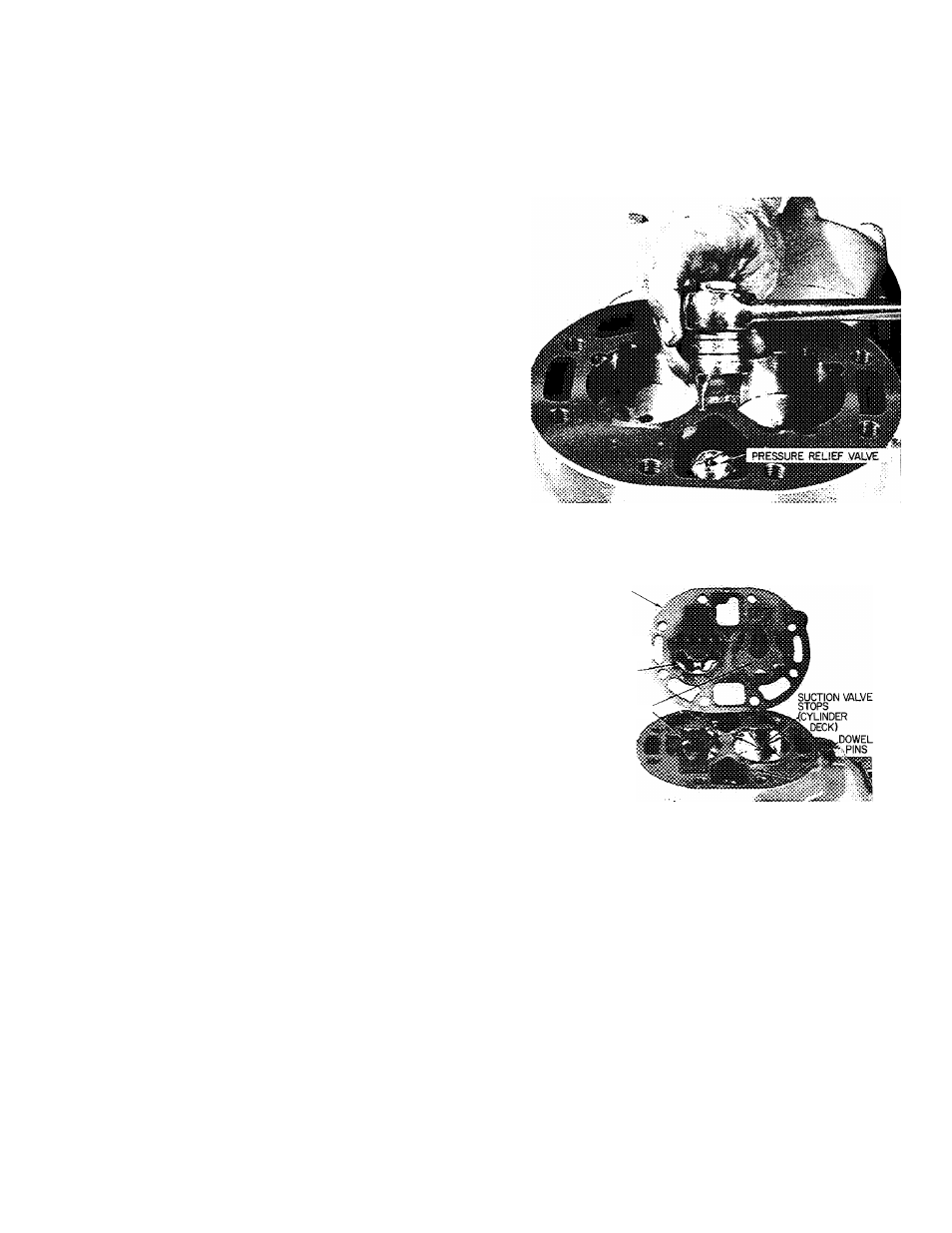
Pressure Relief Valve
— This safety device is
located in center cylinder bank (6-cylinder com
pressors, Fig. 15) or under discharge service valve
(4-cylinder compressors). The valve relieves refrig
erant pressure from high to low side at 400 psi
pressure differential. Check valve for evidence of
leaking. Change if defective or if valve has ever
opened due to excessive pressure. Use a standard
socket-type screwdriver to remove and replace
valve.
SUCTION AND DISCHARGE VALVE
PLATE ASSEMBLY (Fig. 12)
Test
for leaking discharge valves by pumping
compressor down and obseiving suction and
discharge pressure equalization. If a discharge valve
is leaking, their pressures will equalize rapidly.
Maximum allowable discharge pressure drop is 3
psi per minute.
If there is an indicated loss of capacity and
discharge valves check properly, remove suction
and discharge valve plate assembly and inspect
suction valves.
Disassemble
— Remove cylinder head.
1. Remove discharge valve assembly: cap screws,
valve stops, valve stop supports and valves.
2. Pry up on side lifting tab to remove valve plate
and expose suction valves (Fig. 16). Remove
suction valves from dowel pins.
Inspect valves and valve seats for wear and
damage (see Wear Limits, Table 5). Replace valves
if cracked or worn. If valve seats are worn, replace
complete valve plate assembly.
Reassemble
— Do not interchange valves. Install
suction valves on dowel pins. Place valve plate on
cylinder deck, and reinstall discharge valve
assembly. Retorque discharge valve stop cap screws
to 16 Ib-ft. Replace cylinder head. (Be sure tab on
cylinder head gasket is lined up with tabs on
cylinder head and valve plate.)
Fig. 15 — Pressure Relief Valve Removal
VALVE PLATE
SUCTION VALVE ?
SEATS
(VALVE PLATE)
SUCTION VALVES <
Fig. 16 — Valve Plate Removed
TERMINAL PLATE ASSEMBLY
Removal
— Disassemble junction box from termi
nal plate, and remove cap screws holding terminal
plate to compressor. Mark all motor leads so they
can be reassembled correctly to terminal plate.
Loosen alien head screws holding motor leads to
terminal plate (Fig. 17). Remove terminal plate.
Power Lead Terminal Stud
— Disassemble only if
leaking refrigerant or if resistance to ground is low.
If there is a short to ground, replace complete
terminal plate assembly.
DISASSEMBLE (Fig. 18)
1. Unscrew terminal, terminal locknut, and termi
nal bolt assembly hex nut.
11