Electrical requirements, Accessories – Carrier 06E User Manual
Page 3
Attention! The text in this document has been recognized automatically. To view the original document, you can use the "Original mode".
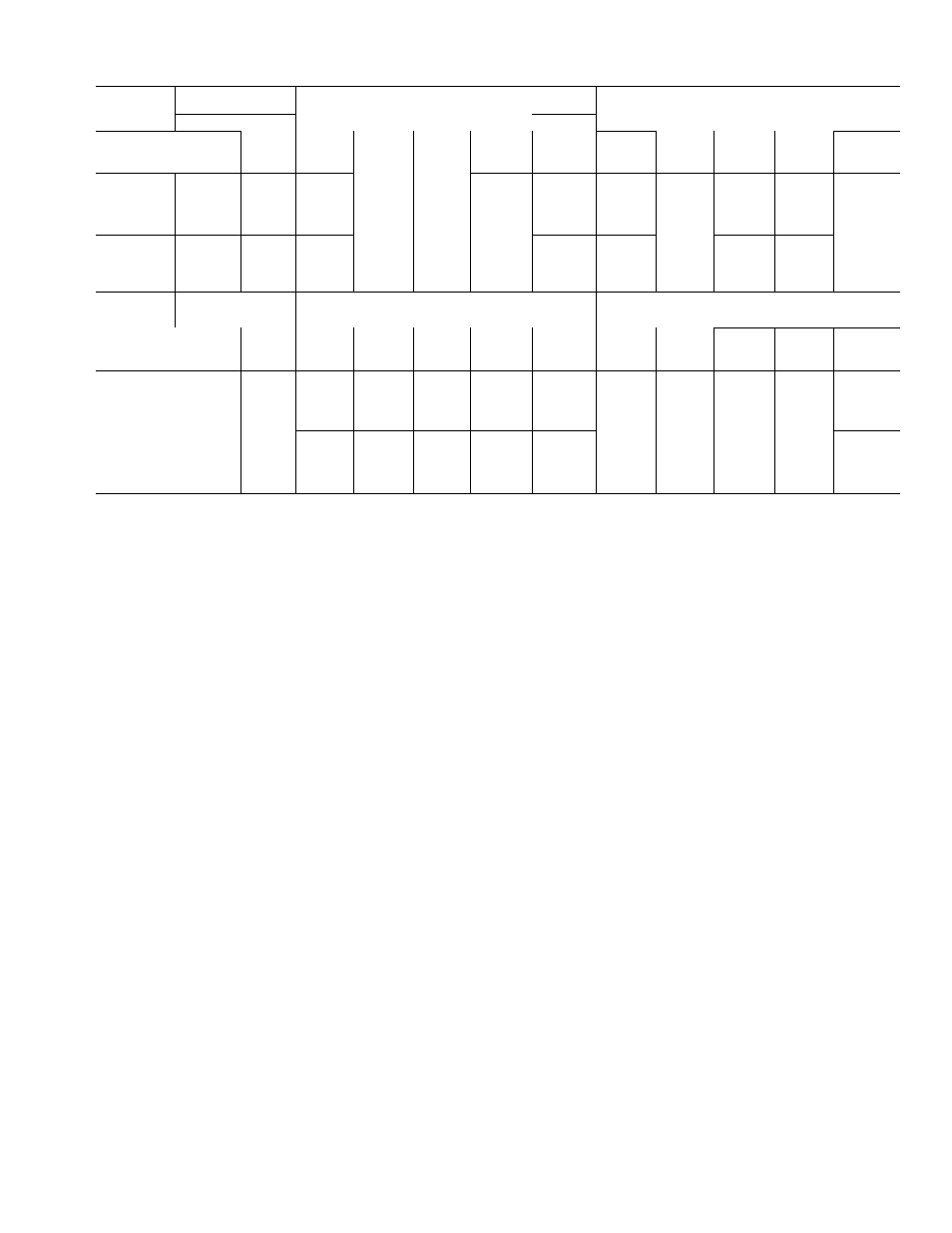
Table 2 — Electrical Data (60-Hertz, 3-Phase)
(Circuit Breakers Selected for Units Using R-22)
VOLTS
Nomina 1
200
230
Supply Range
180-229
207-264
MÀX
MAX
UNIT
KW
RLA
LRA
MTA
MWA
FUSE
RLA
LRA
MTA
MWA
FUSE
AMPS
AMPS
V022
24.8
g2
345
114
102
175
75
300
104
94
150
Compr
W027
33.6
103
471
144
129
225
92
410
128
115
200
06 E
W033
37.6
1 14
506
160
143
250
103
440
144
129
225
W044
55.1
164
690
230
206
350
150
600
210
188
300
A022
22.6
72
283
100
90
150
63
r 246
88
79
125
Cond
B027
31.4
96
471
134
120
200
85
410
118
106
175
07 E
B033
34.0
107
471
150
134
225
96
410
134
120
200
D044
50.4
159
690
222
198
350
140
600
196
175
300
VOLTS
Nominal
460
575 (See Note 5)
Supply Range
414-528
518-660
MAX
MAX
UNIT
KW
RLA
LRA
MTA
MWA
FUSE
RLA
LRA
MTA
MWA
FUSE
AMPS
AMPS
V022
24.8
36
150
50
45
80
29
120
40
37
60
Compr
W027
33.6
45
205
63
56
100
36
164
50
45
80
06 E
W033
37.6
51
220
71
64
no
42
176
58
53
90
W044
55.1
76
300
106
95
150
60
240
84
75
125
A022
22.6
32
123
45
40
70
27
98
37
34
60
Cond
B027
31.4
43
205
60
54
90
33
164
45
42
70
07 E
B033
34.0
48
205
66
60
100
39
164
54
48
80
D044
50.4
70
300
98
88
150
60
240
84
75
125
KW
— Maximum Power Input
LRA
— Locked Rotor Amps
MTA
— Must Trip Amps
MWA
— Minimum Wire Amps Complies with NEC Section
430-22
RLA
— Rated Load Amps
Supply Range — Units are suitable for use on electrical systems
where voltage supplied to the unit terminals is
not below or above the listed range limits
NOTES:
1 Control voltage is 115 v for all units
(Continued from page 1.)
suction line so compressor suction valve may be
moved aside for access to suction strainer.
A solenoid valve is necessary for single pump
out control used on 06E and 07E units. Install the
valve (field supplied) in the liquid line, just before
the expansion valve. A filter-drier of adequate size
should be installed in liquid line between con
denser and solenoid valve.
Pressure relief valve located on side of con
denser will open to relieve excessive pressure,
allowing refrigerant to escape. Most local codes
require piping from valve to outdoors.
Refer to Carrier System Design Manual for
standard piping techniques.
ELECTRICAL REQUIREMENTS
Eield wiring must comply with local and
national codes. See Table 2.
Install a branch circuit fused disconnect of
adequate size to handle starting current. The
disconnect must be within sight of the unit and
readily accessible, in compliance with National
Electrical Code (NEC), Section 440—14.
Line power is brought into control center thru
indicated opening. Connect line power supply to
2 Part-winding start all 200-, 230-volt 06E and 07E units; 460-,
575-volt 06EW044 and 07ED044 units
Across-the-line
start:
all
460-,
575-volt
units
except
06EW044
and 07ED044.
3. Factory wiring is in compliance with National Electrical Code
(NEC)
Field
wiring
must
comply
with
NEC
and
applicable
local
codes
Maximum
incoming
wire
size
to
control
center
terminal block is 250 MCM
4 The 06E compressor unit electrical data shown in the table
does not apply to 06E compressors used as an integral part of
other
Carrier
equipment
Refer
to
the electrical data
for the
particular application
-> 5 Units for use on 575 volts are available on special order
terminal block TB1; connect power leads to
terminals LI, L2 and L3. Connect control circuit
power supply (115 volts) to terminals 1 and 15 on
terminal block TB2. Refer to Eig. 4.
Wiring connections for field-supplied equip
ment are shown on diagram attached to unit (or in
wiring diagram booklet).
Discharge line limit thermostat supplied with
06EV,W compressor units is installed on discharge
line as close to compressor as possible.
1. Place mounting plate on discharge line and
solder in place.
Easten the thermostat to plate with screws
supplied.
Cover switch with insulation and secure insula
tion at each end with straps.
Connect thermostat in series with Ml and M2
overloads, between terminals 2 and 4 on termi
nal block TB2.
ACCESSORIES
2
.
3.
4.
PACKAGE NUMBER
07EA900021
07EA900061
DESCRIPTION
Control
Circuit
Transformer
Gage Panel
1276