Capacity control valve operation (fig. 6), Condenser maintenance (07e units) – Carrier 06E User Manual
Page 7
Attention! The text in this document has been recognized automatically. To view the original document, you can use the "Original mode".
Capacity Control Valve Operation (Fig. 6)
LOADED - When suction pressure is above con
trol point, the poppet valve closes. Discharge gas
bleeds into valve chamber, the pressure closes
bypass piston and cylinder bank loads up. Dis
charge gas pressure forces check valve open, per
mitting gas to enter discharge manifold.
UNLOADED — When suction pressure drops below
valve control point, the poppet valve opens. Dis
charge gas bleeds from behind bypass piston to
suction manifold. Bypass piston opens, discharge
gas is recirculated back to suction manifold and
cylinder bank is unloaded. Reduction in discharge
pressure causes check valve to close, isolating
cylinder bank from discharge manifold.
Table 3 — Steps of Control
COMPRESSOR
STEPS
06 E
1
2
3
CONDENSING
No.
%
No.
%
No.
%
UNIT 07E
Cyl
Cap.
Cyl
Cap.
Cyl
Cop.
06EV022
07EA022
4
100
2
50
-
-
06EW027
07EB027
6
100
4
67
2
33
06EW033
07EB033
6
100
4
67
2
33
06EW044
07 ED 044
6
100
4
67
2
33
NOTE:
Capacity
control
valve
(Fig
7)
factory
settings
for
4-cylinder
units are: 69 psig control set point (cylinder load point), 10 psig
differential
(59
psig
cylinder
unload
point)
Settings
for
6-
cylinder units are: left cylinder bank control set point is 70 psig,
differential is 10 psig; right cylinder bank control set point is 68
psig, differential is 10 psig
Service Replacement Compressors
are not equip
ped with capacity control valves. Side bank
cylinder head(s) is plugged with spring loaded
piston plug assembly(ies). Compressor will run
fully loaded with piston plug(s) in place.
Transfer original capacity control valve(s) to
corresponding
cylinder
bank(s)
in
replacement
compressor
(ensures proper valves are used with
correct setting). Install piston plug assembly(ies)
into original compressor for sealing purposes.
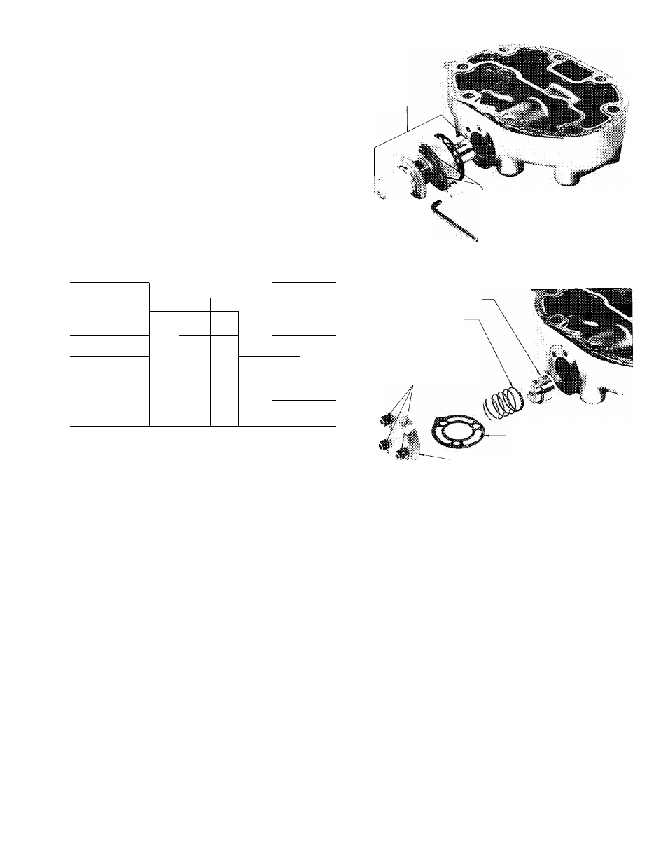
Three alien head cap screws hold capacity
control valve in place (Fig. 8). Remove screws
using a “cut down” 3/16-in. alien wrench, and pull
valve from cylinder head.
Remove same number of piston plugs from
replacement compressor as number of unloaders
supplied with original compressor. Three alien head
cap screws hold piston plug assembly in place.
Remove flange cover, gasket, spring, and piston
plug (Fig. 9). A tapped hole is provided in piston
to allow it to be pulled out. Hole has same thread
diameter as cap screws removed above.
CAPACITY
CONTROL
VALVE
CAP SCREWS
(NONINTERCHANGEABLE
WITH FLANGE COVER
CAP SCREWS)
Fig. 8 — Removal of Capacity Control Valve
BYPASS PISTON PLUG
SPRING
CAP SCREWS
(NONINTERCHANGEABLE
WITH CONTROL VALVE
CAP SCREWS)
GASKET
-FLANGE COVER
Fig. 9 - Removal of Bypass Piston Plug
CONDENSER MAINTENANCE (07E Units)
To inspect and clean condenser, drain water
and remove condenser heads. To drain condenser,
shut off water supply and disconnect inlet and
outlet piping. Remove drain plugs and vent plug.
With condenser heads removed, inspect tubes
for refrigerant leaks. (Refer to Carrier Standard
Service Techniques Manual, Chapter 1, Section
1-6, Leak Testing, for instructions.)
Clean condenser tubes with nylon brush (avail
able from Carrier Service Department). Flush water
thru tubes while cleaning. If hard scale has formed,
clean tubes chemically. Do not use brushes that
will scrape or scratch tubes.
For chemical cleaning solution, use inhibited
hydrochloric acid solution (Oakite 32). Handle
acid cautiously. Clean condenser by gravity or
forced circulation (Fig. 10 and 11). For average
scale deposits allow acid solution to remain in
condenser overnight; for heavy deposits, allow 24
hours. Drain condenser and flush with clean water.
NOTE: Protect condenser from freezing when
ambient is below 32 F by draining water from
system or adding antifreeze to water.