Table 5 — wear limits — 06e compressor, Motor removal, Fig. 18 — power lead terminal stud assembly – Carrier 06E User Manual
Page 12
Attention! The text in this document has been recognized automatically. To view the original document, you can use the "Original mode".
2. Push terminal bolt thru terminal plate and
remove insulating washers.
Inspect for grounds, insulation breakdown, and
sufficient life remaining in terminal seal bush
ings. It is recommended that disassembled
terminal stud assemblies be replaced with new
parts.
REASSEMBLE
1. Refer to Fig. 18 for position of terminal
assembly parts (washers are color coded).
2. Tighten terminal bolt assembly hex nut only
enough to stop escape of refrigerant gas (max
imum recommended torque is 4 Ib-ft). Do not
tighten nuts so terminal insulation washers are
flush with mounting plate.
Table 5 — Wear Limits — 06E Compressor
ALLEN
HEAD
SCREWS (T)
COMPRESSOR PART
MOTOR END
Main Bearing Diameter
Journal Diameter
PUMP END
Main Bearing Diameter
Journal Diameter
CONNECTING ROD
Bearing Diameter
(After Assembly)
Crankpin Diameter
THRUST WASHER
(Thickness)
CYLINDERS
Bore
Piston Diameter
Wrist Pin Diameter
Con. Rod Wrist Pin ID
Piston Ring End Gap
Piston Ring Side
C learance
FACTORY
TOL. (in.)
Max
VALVE
THICKNESS
D ischarge
END CLEARANCE
Suctic
1 .8760
6260
1 7515
2 6885
8755
007
003
0315
0255
0225
031
1 8725
6233
7483
155
2 6817
8748
002
001^
0305
0245*
0215
MAXIMUM
ALLOWABLE
WEAR* (in.)
001
"
001
"
002
*
002
002
001
001
015
002
002
002
010
""Maximum
allowable
wear
above
maximum
or
below
minimum
factory
tolerances
shown
For
example
difference
between
main
bearing
diameter
and
journal
diameter
is
0035
in
(1 8760 — 1 8725) per factory tolerances Maximum allowable
difference is 0045 in (0035+ 001)
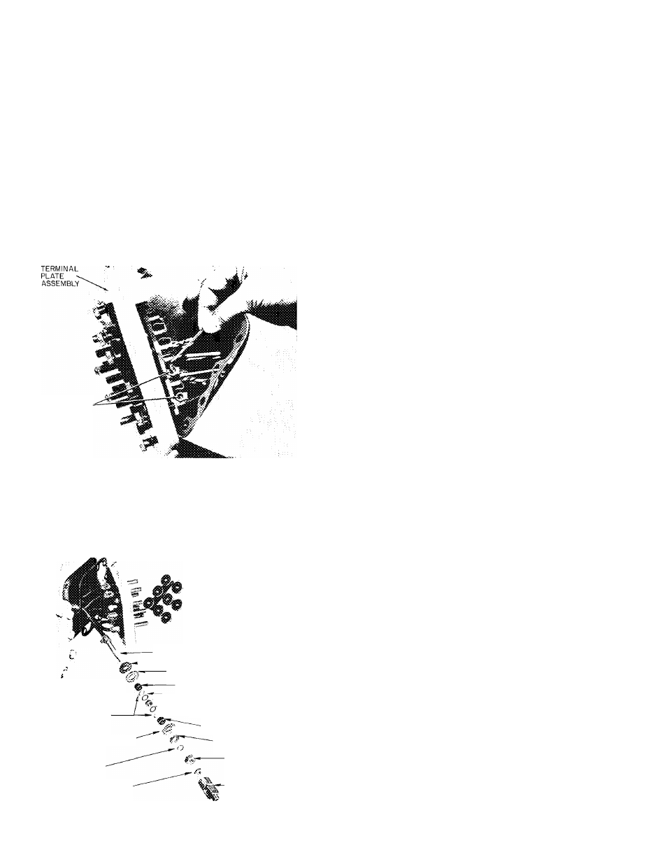
Fig. 17 — Removing Terminal Plate Assembly
■r--7.7X
TERMINAL
INSULATION
WASHERS(GRAY)
TERMINAL
INSULATION
WASHER
LOCK WASHER
(SPRING)
TERMINAL LOCKNUT
TERMINAL BOLT ASSEMBLY
TERMINAL INSULATION WASHER
INSULATION WASHER
■TERMINAL INSULATION BUSHING
-----TERMINAL SEAL BUSHING
TERMINAL SEAL WASHERS
(RED)
TERMINAL INSULATION
BUSHING
PLATE WASHER
HEX NUT
■TERMINAL
Fig. 18 — Power Lead Terminal Stud Assembly
MOTOR REMOVAL
Motor End Bell
— Remove motor end bell care
fully to prevent damage to the stator. Use three
7/16 — 1 4 x 5 in. studs for guides and support. In
spect suction strainer in end bell. Clean it with sol
vent or replace if broken or corroded.
Rotor
— Bend rotor lock washer tab backward and
remove rotor lock bolt. If crankshaft turns, pre
venting lock bolt from being loosened, remove a
cylinder head and valve plate and place a rubber
plug (06R suction plug) on top of one piston (Fig.
19). Replace valve plate assembly and cylinder
head (only two bolts required to hold cylinder
head in place). Proceed to remove rotor lock bolt,
lock washer and plate washer.
Use a jackscrew to remove rotor (Fig. 19).
Insert a brass plug into rotor hole to protect end of
crankshaft from jackscrew. Support rotor while it
is being removed to prevent stator damage. Re
move ring spacer between rotor and crankshaft.
Clean rotor thoroughly with solvent. If stator is
to be replaced, a matching rotor must be used.
12