Initial start-up – Carrier 06E User Manual
Page 4
Attention! The text in this document has been recognized automatically. To view the original document, you can use the "Original mode".
REFRIGERANT
CHARGING
Evacuate, Dehydrate and Leak Test
the entire
refrigerant system by methods described in Carrier
Standard Service Techniques Manual, Chapter 1,
Sections 1-6 and 1-7. Use sight glass method to
charge system. See Section 1-8 of Service Tech
niques Manual for details.
CHARGE THE SYSTEM to a clear sight glass while
holding saturated condensing pressure constant at
125 F (air-cooled systems) or 105 F (water-cooled
systems) Add additional refrigerant to fill con
denser subcooler coils.
07E Condensing Units - After clear sight glass is
obtained, add charge until liquid refrigerant
reaches condenser liquid level test cock.
06E Compressor Units — See condenser data for
additional charge required to fill subcooler.
All Units — Stamp type of refrigerant and amount
of charge on unit informative plate
INITIAL START-UP
Crankcase heater should be energized a mini
mum of 24 hours before starting unit.
Check to see that oil level is approximately 1/3
up on the compressor sight glass.
Open water supply valve and allow water to
reach condenser. (Turn condenser fan on when the
compressor unit is applied with air-cooled con
denser.)
Backseat the compressor suction and discharge
shutoff valves, open liquid line valve at receiver.
Start evaporator fan or chilled water pump.
Start Compressor
— Push the control circuit
START-STOP-RESET switch to “Start.” The timer
motor starts immediately. Depending on the posi
tion of the timer, the compressor start is delayed
for 12 seconds to approximately 8 minutes. Check
oil pressure after compressor has run a few
minutes, the pressure should be 12—18 psi above
the suction pressure After about 20 minutes of
operation, stop the compressor. Allow it to be idle
for about 5 minutes, then observe the oil level in
the sight glass. If the oil level is below the bottom
of the sight glass, refer to the Carrier Standard
Service Techniques Manual, Chapter 1, Section
1-11, for adding oil. The proper oil level for the
06E compressor is approximately 1/3 up on sight
glass.
là
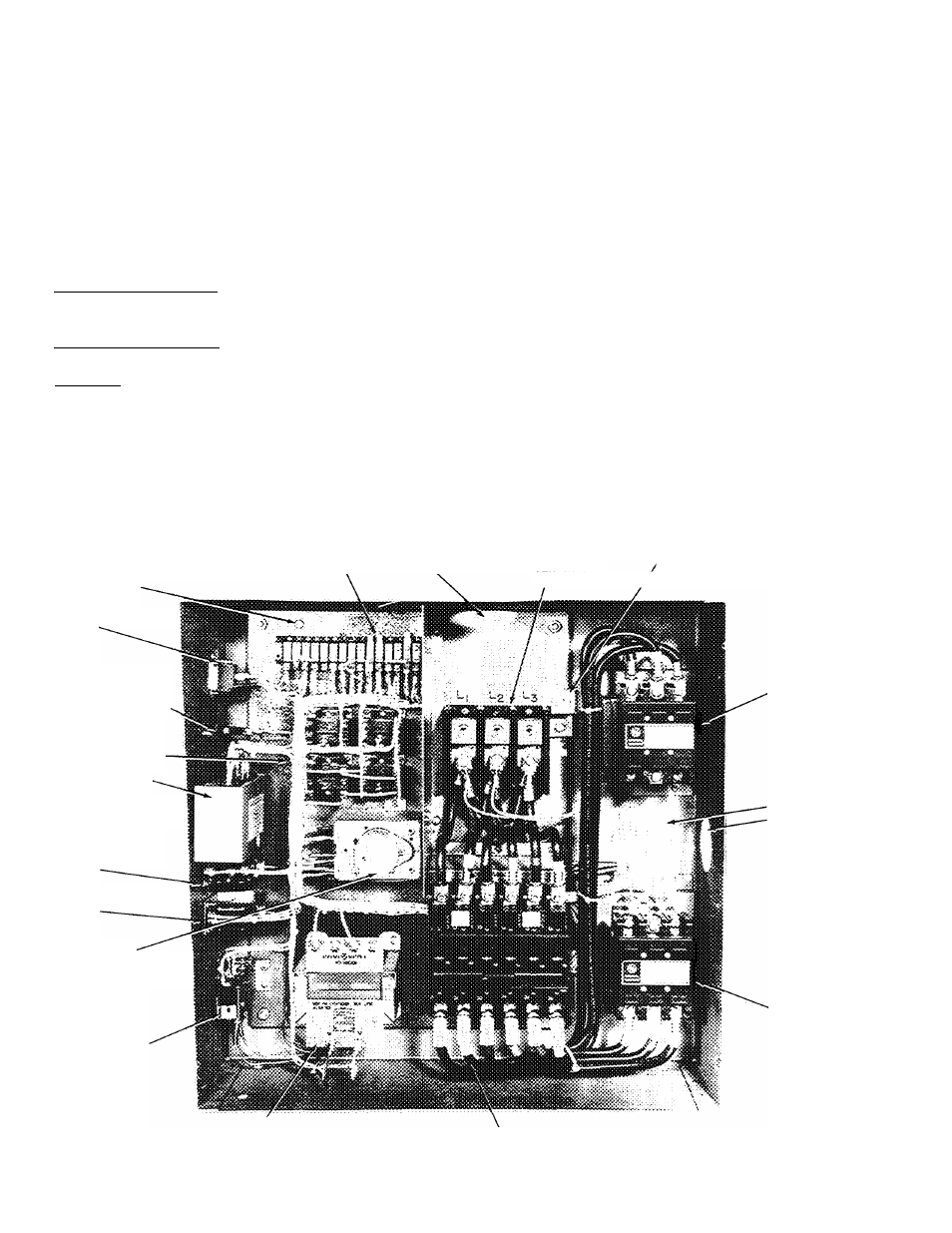
CONTROL POWER TERMINAL STRIP (TBg)
GROUND SCREW
START-STOP-RESET
SWITCH
MAIN POWER
INLET,
MAIN POWER
TERMINAL
BLOCK (TB|)
EQUIPMENT GROUND
'
connection
CONTROL CIRCUIT
FUSE(S)
(2 ON 50-Hz UNITS)
CONTROL RELAYS
SENSOR MODULE
(SOLID STATE
COMPRESSOR MOTOR
PROTECTION)
COMPRESSOR
CONTACTOR
OUTLET FOR
WIRING TO
COMPRESSOR
06E
07E
HIGH PRESSURE
SWITCH
LOW PRESSURE
SWITCH
TIMER MOTOR
(4-FUNCTION TIMER)
OIL PRESSURE
SAFETY SWITCH
COMPRESSOR
CONTACTOR
(PART-WIND)
ACCESSORY TRANSFORMER
(60-Hz UNITS ONLY)
MAIN POWER
CIRCUIT BREAKER
Fig. 4 — Control Center — 06E and 07E
1276
4