Appendix a – connector pin outs – USL DAX-16 User Manual
Page 20
DAX-‐16 Installation & Operation Manual
Rev 1.4
20
Appendix A – Connector Pin Outs
DE-‐15F
Amplifier
Outputs
The
DAX-‐16
has
eight
DE-‐15F
connectors
to
drive
power
amplifiers.
DE-‐15F Signals by Pin
Pin Signal
1
Channel A – input
2
Standbyn – Pulled low to put amplifier in standby
3
Channel A Vmon (output voltage monitor)
4
Channel
A
Imon
(output
current
monitor
–
not
used
on
DAX-‐16)
5
No Connect
6
Chassis Ground (shield)
7
Channel A +input
8
Channel B +input
9
+15V from amplifier (not used by CM-‐8E)
10
Signal Ground (reference for Vmon and Imon)
11
Channel B –input
12
No Connect
13
Channel B Vmon (output voltage monitor)
14
Channel
B
Imon
(output
current
monitor,
not
used
by
DAX-‐16)
15
No Connect
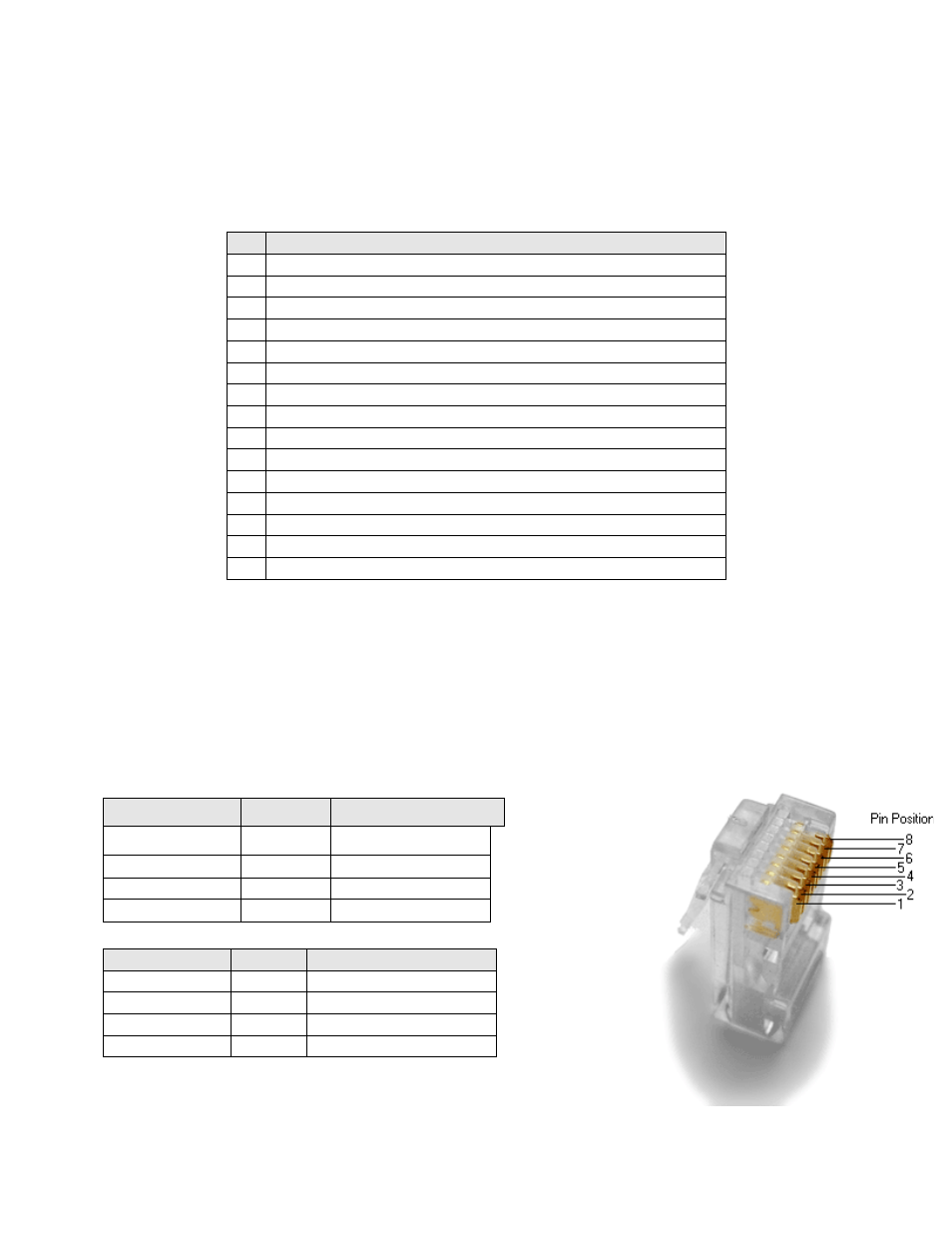
RJ-‐45
AES
Input
The
DAX-‐16
uses
the
StudioHub
pin
out
for
AES/EBU
over
CAT5
or
CAT6
Ethernet
cable.
These
cables
are
twisted
pair
and
have
the
required
characteristic
impedance.
The
top
RJ-‐45
connector
carries
digital
audio
inputs
1
through
8.
The
bottom
RJ-‐45
connector
carries
digital
audio
inputs
9
through
16.
Audio
Channels
AES Pair
Top RJ-‐45 Pins ( +, -‐ )
1, 2
1
1, 2
3, 4
2
3, 6
5, 6
3
4, 5
7, 8
4
7, 8
Audio
Channels
AES
Pair
Bottom
RJ-‐45
Pins
(
+,
-‐
)
9, 10
5
1, 2
11, 12
6
3, 6
13, 14
7
4, 5
15, 16
8
7, 8