Front panel, Rear panel – USL DAX-16 User Manual
Page 11
DAX-‐16 Installation & Operation Manual
Rev 1.4
11
Front Panel
The
DAX-‐16
front
panel
includes
signal
presence
indicators
for
each
output.
The
LED
lights
when
a
channel
has
an
output
level
of
10.7mV
RMS
or
higher.
The
front
panel
is
marked
with
typical
output
assignments
for
biamp
and
triamp
operation
(as
explained
in
the
DAX-‐16
Output
Assignments
section,
below),
but
any
output
can
reproduce
audio
from
any
digital
input.
Installers
may
want
to
place
a
label
tape
over
the
silk
screened
labels
to
represent
the
speaker
assignments
in
the
auditorium
(especially
when
multiple
DAX-‐16
units
are
stacked).
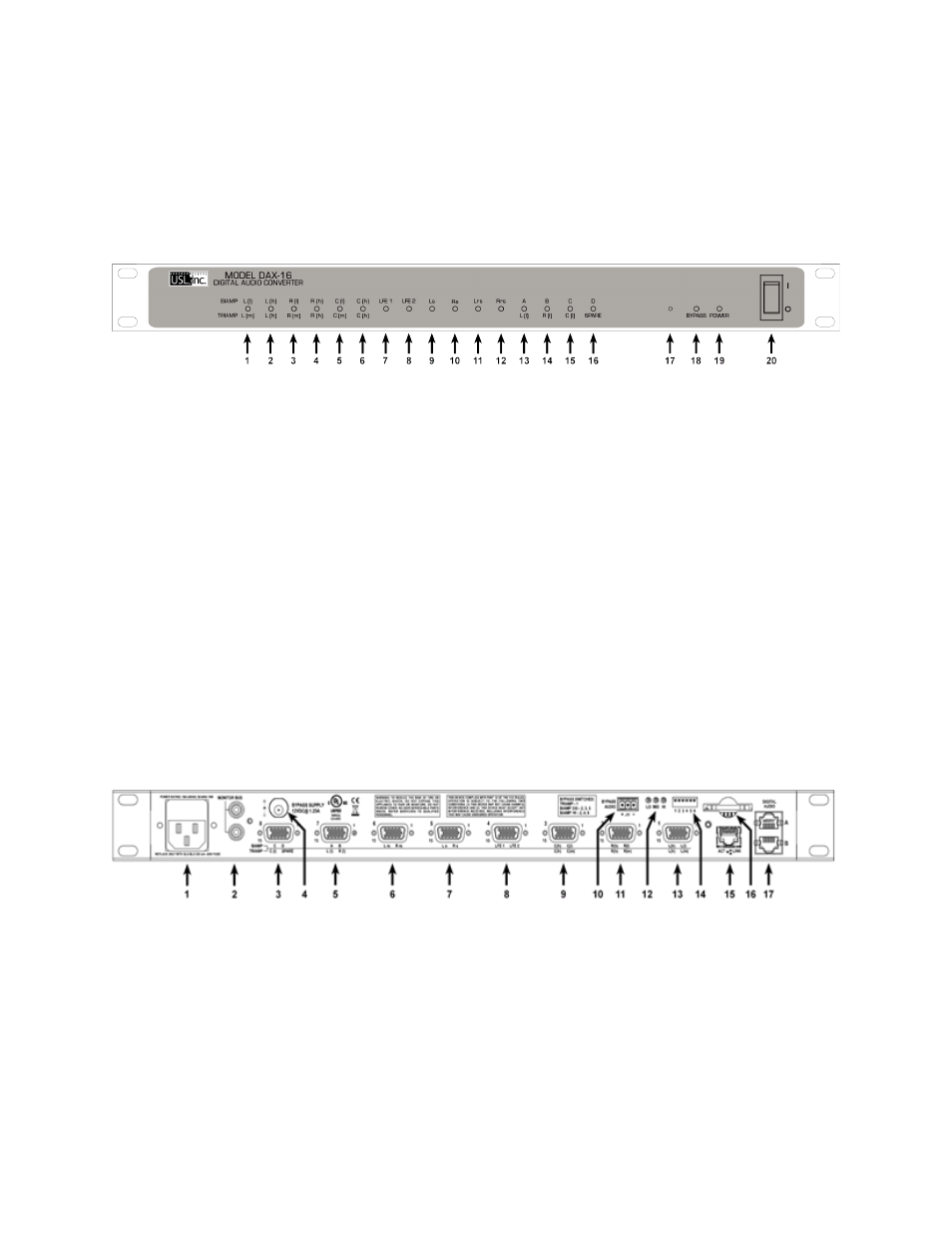
Figure 2 -‐ DAX-‐16 Front Panel
Figure
2
shows
the
front
panel
of
the
DAX-‐16.
Items
1
through
16
are
the
signal
presence
LEDs.
LEDs
1
and
2
correspond
to
outputs
1A
and
1B
on
the
DE-‐15
output
connector
number
1.
Similarly,
LEDs
3
and
4
correspond
to
outputs
2A
and
2B.
Item
17
is
the
system
restore
button.
It
can
be
pressed
with
a
paper
clip
and
serves
two
purposes.
If
the
button
is
held
down
as
power
is
applied,
the
factory
firmware
is
restored
to
the
system.
This
can
be
done
in
the
unlikely
event
of
a
firmware
update
failure.
If
the
button
is
pressed
momentarily
after
the
system
has
powered
up
(after
the
front
panel
LEDs
have
stopped
flashing),
the
configuration
on
the
SD
card
is
copied
into
the
system
and
to
flash
memory.
This
allows
a
system
to
be
easily
replaced
by
just
moving
the
SD
card
and
restoring
the
configuration.
Item
18
is
the
bypass
status.
This
LED
is
lit
steadily
if
the
system
has
bypass
power
applied.
The
LED
flashes
if
the
analog
bypass
signal
is
being
used
instead
of
the
digital
signal.
See
DAX-‐16
Output
Assignments
for
more
information
on
analog
bypass.
Item
19
is
the
power
LED
that
lights
if
main
power
is
applied
and
the
main
power
switch
(item
20)
is
on.
Rear Panel
Figure 3 -‐ DAX-‐16 Rear Panel
The
DAX-‐16
rear
panel
is
shown
in
figure
3.
Each
item
is
described
below.
1. AC power input. The DAX-‐16 operates from 100 – 240VAC and consumes about 15W. Use the supplied
line cord or a 3 conductor line cord appropriate for your location.
2. Monitor bus. The audio streaming monitor bus can be cascaded between units so the stream from a
single
unit
can
contain
audio
from
several
units.
Use
a
short
RCA
cable
to
link
two
DAX-‐16s
together.
Either
connector
may
be
used.
Typically
the
top
connector
is
used
to
link
to
a
DAX-‐16
higher
in
the
rack
and
the
bottom
connector
is
used
to
link
to
a
DAX-‐16
lower
in
the
rack.