Figure 3-12 – Cisco 3750 User Manual
Page 50
3-10
Catalyst 3750 Metro Switch Hardware Installation Guide
OL-9160-02
Chapter 3 Connecting the Power Supply
Connecting to DC Power
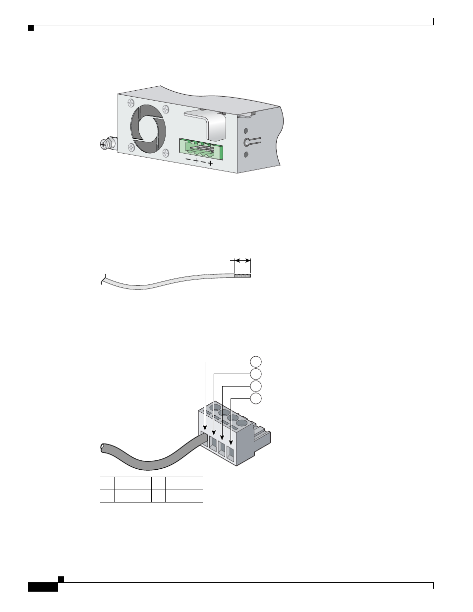
Figure 3-12
Positive and Negative Positions
Step 3
Using an 18-gauge wire-stripping tool, strip each of the four wires coming from the DC-input power
source to 0.27 inch (6.6 mm) ± 0.02 inch (0.5 mm). Do not strip more than 0.29 inch (7.4 mm) of
insulation from the wire. Stripping more than the recommended amount of wire can leave exposed wire
from the terminal block plug after installation. (See
Figure 3-13
Stripping the DC-Input Power Source Wire
Step 4
Insert the exposed wire of one of the four DC-input power source wires into the terminal block plug, as
shown in
. Make sure that you cannot see any wire lead. Only wire with insulation should
extend from the terminal block.
Figure 3-14
Inserting Wires in the Terminal Block Plug
97466
0.25 in. (6.3 mm) ± 0.02 in. (0.5 mm)
60531
1
Negative
3
Negative
2
Return
4
Return
97481
1
2
3
4