Connecting the grounding wire to earth ground, Installing the dc power supply in the switch – Cisco 3750 User Manual
Page 47
3-7
Catalyst 3750 Metro Switch Hardware Installation Guide
OL-9160-02
Chapter 3 Connecting the Power Supply
Connecting to DC Power
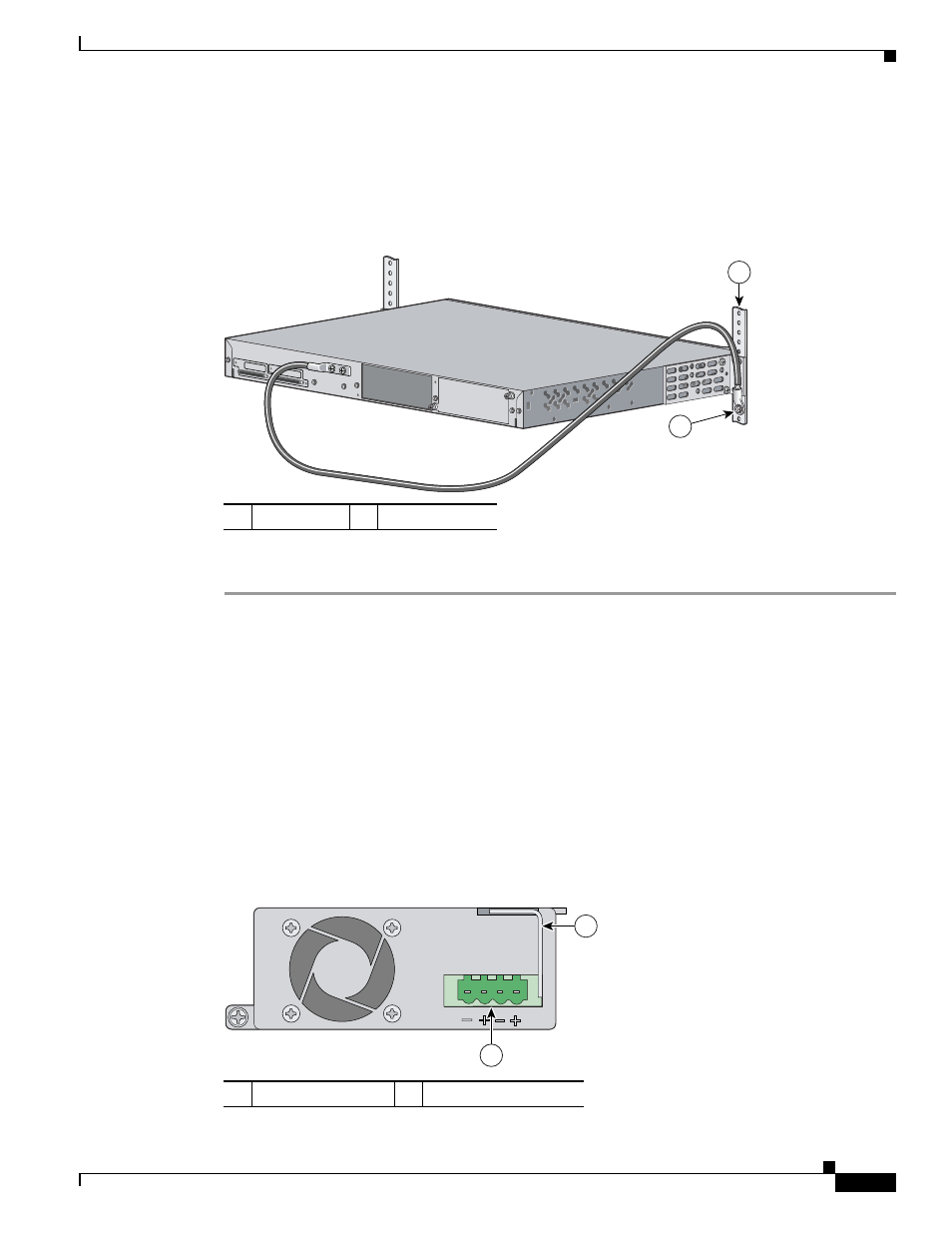
Connecting the Grounding Wire to Earth Ground
Next you must connect the other end of the grounding wire to an appropriate grounding point at your
site or to the telco rack (see
Figure 3-7
Connecting the Grounding Wire to the Rack
Complete these steps:
Step 1
Remove all paint or oxidation from the rack at the point of the grounding connection.
Step 2
Use a 3/16-inch flat-head screwdriver to loosen the grounding screw on the rack.
Step 3
Connect the wire to a ring lug (large enough for the rack screw to fit through).
Step 4
Use a 3/16-inch flat-head screwdriver and the screw to attach the ring lug to the rack.
Step 5
Tighten the grounding screw on the rack over the ring lug.
Repeat these steps for each switch being installed.
Installing the DC Power Supply in the Switch
shows the location of the DC power supply parts.
Figure 3-8
DC Power Supply
1
Telco Rack
2
Grounding wire
STACK 1
STACK 1
97961
1
2
1
Power-on restrictor
2
DC-power connector
97468
1
2