Rear panel description, Power connectors, Power supply connector – Cisco 3750 User Manual
Page 17: Management options
1-7
Catalyst 3750 Metro Switch Hardware Installation Guide
OL-9160-02
Chapter 1 Product Overview
Rear Panel Description
Rear Panel Description
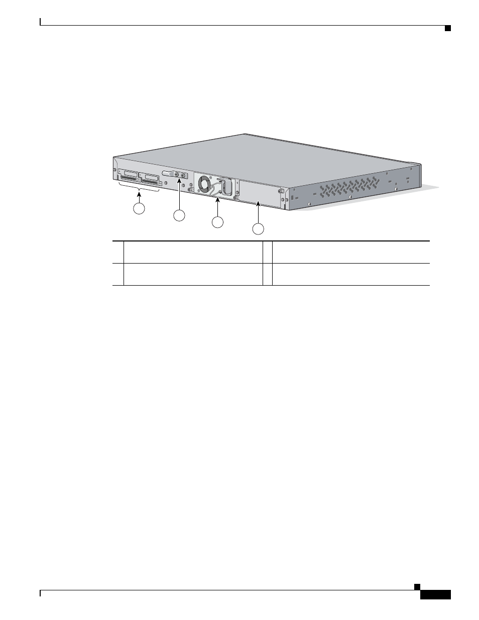
The switch rear panel has two power slots, a grounding lug, and two StackWise ports (not used). (See
Figure 1-3
Catalyst 3750 Metro Switch Rear Panel
Power Connectors
A power supply that is installed in power slot A powers the switch. This power supply is a
field-replaceable unit (FRU). You can connect an optional FRU power supply in slot B to provide backup
power if power supply A fails. You can power the switch by using either an AC power supply, a DC
power supply, or a combination of the two.
Power Supply Connector
The power supply is an autoranging unit that supports input voltages between 100 and 240 VAC. Use the
supplied AC power cord to connect the AC power connector to an AC power outlet. See
“Connecting the Power Supply,”
for instructions on how to connect the DC power.
Management Options
The switch offers several management options:
•
Cisco IOS command-line interface (CLI)
You can fully configure and monitor the switch from the CLI. You can access the CLI either by
connecting your management station directly to the switch console port or by using Telnet from a
remote management station. See
Appendix C, “Configuring the Switch with the CLI-Based
and refer to the Catalyst 3750 Metro Switch Command Reference on Cisco.com for
more information about using the CLI.
1
StackWise ports (not used)
3 Power slot A (shown with an installed AC
power supply)
2
Grounding lug (used with a DC power
supply)
4 Power slot B
97425
1
STACK 1
STACK 1
3
4
2