Verifying switch operation, Connecting a pc or terminal to the console port, Powering on the switch and running post, page 2-7 – Cisco 3750 User Manual
Page 24: 9600 baud, 8 data bits, 1 stop bit, No parity, None (flow control), 1console port
2-6
Catalyst 3750 Metro Switch Hardware Installation Guide
OL-9160-02
Chapter 2 Switch Installation
Preparing for Installation
Verifying Switch Operation
Before installing the switch in a rack, on a wall, or on a table or shelf, you should power the switch and
verify that the switch passes POST. These sections describe the steps required to connect a PC to the
switch console port and to power on the switch:
•
Connecting a PC or Terminal to the Console Port, page 2-6
•
Powering On the Switch and Running POST, page 2-7
Connecting a PC or Terminal to the Console Port
To connect a PC to the console port, use the supplied RJ-45-to-DB-9 adapter cable. To connect the switch
console port to a terminal, you need to provide a RJ-45-to-DB-25 female DTE adapter. You can order a
kit (part number ACS-DSBUASYN=) containing that adapter from Cisco. For console port and adapter
pinout information, see the
“Cable and Adapter Specifications” section on page B-5
.
You can use terminal-emulation software—frequently a PC application such as Hyperterminal or
Procomm Plus—to make communication between the switch and your PC or terminal possible.
Follow these steps to connect the PC or terminal to the switch:
Step 1
Configure the baud rate and character format of the PC or terminal to match these console port default
characteristics:
•
9600 baud
•
8 data bits
•
1 stop bit
•
No parity
•
None (flow control)
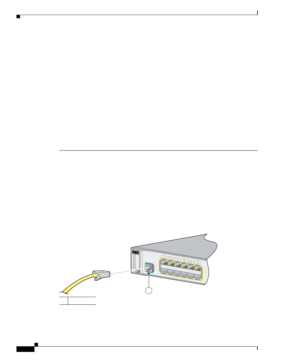
Step 2
Use the supplied RJ-45-to-DB-9 adapter cable to insert the RJ-45 connector into the console port, as
shown in
.
Figure 2-1
Connecting to the Console Port
1
Console port
97463
1
2
3
4
5
6
7
8
9
10
11
12
1X
2X
11X
12X
CONSOLE
PWR A
SYST
PWR B
MASTR
STAT
DUPLX
SPEED
STACK
MODE
1