Re (see, Figure 3-5 – Cisco 3750 User Manual
Page 46
3-6
Catalyst 3750 Metro Switch Hardware Installation Guide
OL-9160-02
Chapter 3 Connecting the Power Supply
Connecting to DC Power
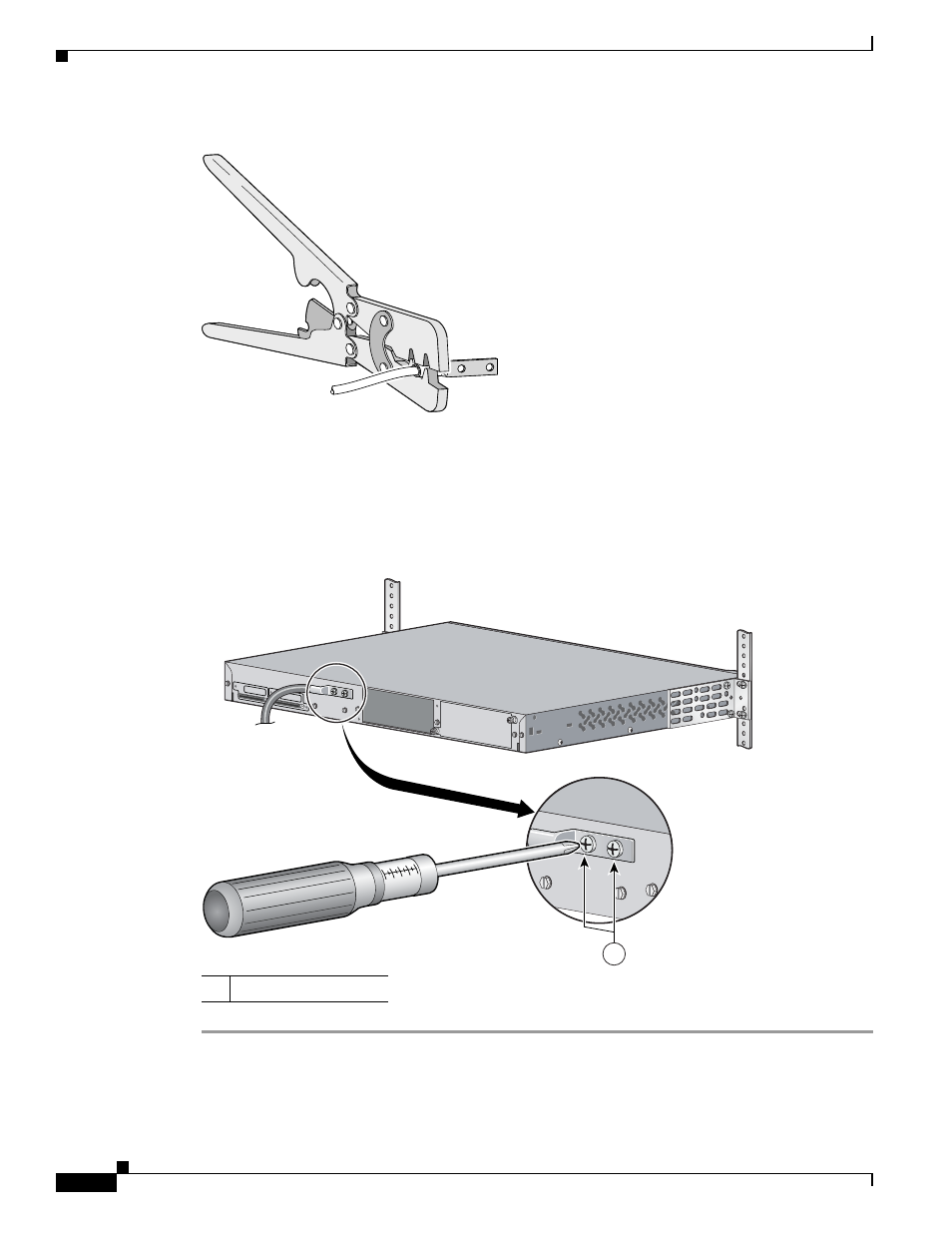
Figure 3-5
Crimping the Ground Lug
Step 5
Use the two number-10-32 screws to attach the ground lug and wire assembly to the rear panel of the
switch.
Step 6
Using a ratcheting torque screwdriver, torque each grounding-lug screw to 15 lbf-in. (240 ounce-force
inches [ozf-in.]).
shows how to torque the grounding-lug screws on a switch.
Figure 3-6
Torquing Ground-Lug Screws
60529
1
Grounding-lug screws
STACK 1
STACK 1
97470
1