Top Flite TOPA0101 User Manual
Page 7
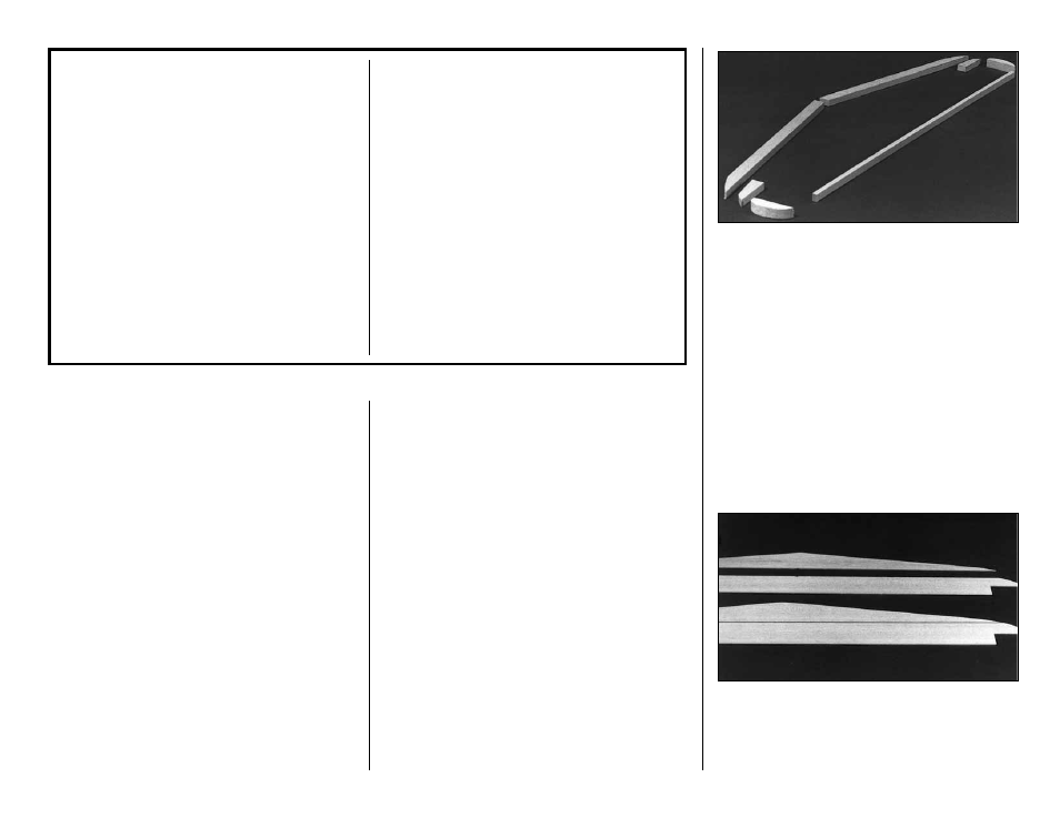
Sanders
are made from lightweight extruded
aluminum and can be found at most hobby shops.
They are available in three sizes – 5-1/2"
(GPMR6169) – 11" (GPMR6170) for most general
purpose sanding and 22" (GPMR6172) for long
surfaces such as wing leading edges. We
recommend using the 2" wide self-adhesive
sandpaper sold in 12' rolls by Great Planes.
Standard sandpaper can be attached by gluing it
to the sander with brush-on rubber cement. Apply
the rubber cement to both the bottom of the
sander and the back of the sandpaper. When both
surfaces are dry to the touch, press the sandpaper
firmly onto the sander. Spray adhesive can be
used for this purpose but it’s much harder to
remove the sandpaper when you need to replace
it. Use a knife blade for cutting sandpaper, not
your good scissors!
GET READY TO BUILD
❏
1. Unroll the plan sheets. Reroll the plan sheets
inside out to make them lie flat.
❏
2. Remove all parts from the box. As you do,
determine the name of each part by comparing it
with the plan. Using a felt-tip pen, write the part
name or size on each piece to avoid confusion later.
Use the die-cut patterns shown on pages 4 and 5 to
identify the die-cut parts and mark them before
punching out. Save all scraps. If any of the die-cut
parts are difficult to punch out, do not force them!
Instead, first cut around the parts with a hobby knife.
After punching out the die-cut parts, use your bar
sander or sanding block to lightly sand the edges to
remove any die-cutting irregularities.
❏
3. As you identify and mark the parts, separate
them into groups, such as fuse (fuselage), wing, fin
and stab (stabilizer), and hardware.
BUILD THE STAB
❏
1. Arrange the
stab
portion of the plan on a
flat building board (you may wish to cut out the
stab section). Cover the area over the stab with
waxed paper.
7
OTHER ITEMS REQUIRED
❏
Four-Channel Radio with 4 servos (additional
channels and servos required if retracts and/or
flaps are used).
❏
Top Flite Power Point
®
Propellers (see engine
instructions for recommended sizes)
❏
Prop Safety Nut (Great Planes has sizes and
styles that work nicely)
❏
12 oz Fuel Tank (DUBQ0212)
❏
5/32" Wheel Collars - 4 (GPMQ4306)
❏
3/32" Wheel Collars - 2 (GPMQ4302)
❏
Top Flite MonoKote Covering Material (Insignia
Blue and Yellow)
❏
Fuelproof Paint* for Cowl, Canopy and Oil
Coolers (Top Flite LustreKote
™
recommended)
❏
Latex Foam Rubber Padding, 1/4" thick
(HCAQ1000)
❏
Silicone Fuel Tubing (GPMQ4131)
❏
Plastic Pilot: Williams Bros. Standard, 2" Scale
#17600 (WBRQ1050)
❏
Main Gear Retracts (optional)...Robart #615
(ROBQ1815) Century Jet 33325 - complete
kit (CJMQ3055)
❏
Air Control Kit (optional retracts)...Robart
#188VRX (ROBQ2307) (Not required with CJ
33325)
❏
Oleo Robo Struts (optional)...Robart #650
(ROBQ1700) (Not required with CJ 33325)
❏
Hinge Points (optional flaps)...Robart #308
(ROBQ2508)
❏
3-1/4" Main Wheels...Robart #134 (ROBQ1534)
❏
1-1/4 Tail Wheel (GPMQ4242)
❏
.60 to .80 2-stroke, .90 to 1.20 4-stroke
NOTE:
Top Flite “LustreKote Paint” matches
MonoKote covering and is available in aerosol cans.
❏
2. Cut the balsa 3/8" x 5/8" x 24"
LE stock
to fit
nicely at the center joint. Save excess material for
the fin LE. Trim the tip of the LE to the approximate
shape on the plan but leave about 1/16" excess for
final shaping later.
❏
3. Cut the balsa 1/4" x 3/8" x 30"
TE stock
to
the correct length. Extra material is kept for the Fin.
❏
4. Cut the two
elevator tip blocks
from the 1/2"
x 1/2" x 4" balsa stick provided. Shape the tips to
match the plan shape.
❏
5. Make the
stab tips
from excess 3/8" x 5/8" LE
stock. Set the previously made parts aside for now.
❏
6. Make a top and bottom stab skin by placing
the 1/16" die-cut balsa pieces,
stab front
and
stab
back
, together over waxed paper and glue them
together with thin CA. Block sand the skins lightly
with 220-grit sandpaper.