Top Flite TOPA0101 User Manual
Page 20
❏
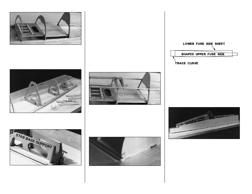
12. If you are
installing the optional cockpit kit,
glue
F-7
and the
cockpit deck
in position as
indicated in the photo. Otherwise, trim off both edges
of the cockpit deck along the precut lines and install it
in the notches in the upper part of the formers.
❏
13. Glue
F-8, F-9 and F-10
to the main stringers
over their location on the plan. Be sure the pushrod
holes are properly oriented.
❏
14. Trial fit F-11 on the main stringers. Test the fit
of the
stab base supports
in between
F-10
and
F-11
. The stab base support should rest flat on the
building board along its entire length.
This is very
important as it sets the stab incidence
. Remove a
little material from the interlocking joints if necessary
to allow the stab base support to rest on the building
board. Glue the stab base support and F-11 in
position with medium CA.
NOTE:
If you are installing the optional cockpit kit,
install the instrument panel as shown in the following
steps. Otherwise, the instrument panel is glued to the
base of the cockpit deck 1-1/16" behind F-5.
❏
15. Glue all the upper stringers in place as
shown in the photograph. Check the formers with a
90 deg. triangle during this process to make sure
they are vertical.
❏
16. Fit the Instrument Panel into the stringers
1-1/16" to the rear of F-5. Insure that it is parallel
with F-5 and then glue it into position.
❏
17. With a sanding block, smooth any glue joints
that will affect the sheeting of the fuselage. Sand the
main stringers slightly to blend with the formers.
❏
18. Glue the four 1/8" x 1/4" x 24" balsa
sub
stringers
into the slots in each of the main
stringers. These will provide a shelf for the
sheeting to rest on.
NOTE:
It is helpful to put some weight in the cockpit
to hold the fuse firmly on the building board. Leave
the fuse on the building board during sheeting.
❏
19. Locate the 3/32" x 4" x 36" balsa
lower fuse
side sheets
. Place the shaped 3/32" balsa
upper
fuse side
over the lower fuse side sheets. Trace
the “bow” of the bottom edge of the upper fuse
side sheet onto the lower fuse side sheets as
shown in the sketch. Set the lower fuse side sheets
aside until they are needed.
❏ ❏
20. Pin a shaped 3/32" balsa fuse side on
the fuselage frame. Align the rear edge of the fuse
side with the rear of F-12. Notice that the bottom
edge of the fuse side is curved up slightly. This
allows the wood to bend around the fuselage
frame without lifting the center of the fuselage off
the building board.
NOTE:
A small amount of water applied to the
outside of the fuse side with a paper towel is
helpful when bending the fuse sides.
20