Top Flite TOPA0101 User Manual
Page 31
edge of the
engine mount.
Mark, drill and tap the
engine mounting holes to accept 8-32 socket head
cap screws.
❏
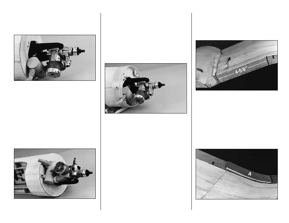
6. Center your engine mount over the lines you
drew on the face of the firewall. Mark and drill the
engine mount holes in the firewall. Install the engine
mount on the firewall with four 8-32 x 2" socket head
cap screws, #8 flat washers and #8 lock washers.
Cut off the excess screw length, if any, that
protrudes into the tank compartment.
NOTE:
The firewall is already marked for the
45 degree inverted position.
❏
7. Drill holes in the firewall for the fuel lines and
the throttle pushrod. The location of these holes will
depend on the engine installation you choose.
❏
8. Before mounting the muffler you will have to
modify the Top Flite Engine Exhaust Header (not
included) and the Top Flite In-Cowl Muffler (not
included). Trim 3/8" from the outlet end of the
Engine Exhaust Header and 1/8" from the Muffler
inlet. Other engine and muffler combinations will
require different modifications. Bolt the Top Flite
Header to the engine. Use the Silicone Sleeve to
attach the Top Flite In-Cowl Muffler to the header.
Mount the Muffler to the firewall with the supplied
screws and silicone washers.
❏
9. Place the molded plastic aft cowl ring on the
front of the model. The 1/8" mounting holes are
rotated 45 degrees from the horizontal and vertical
axis as shown in the photos. These holes may have
to be relocated depending on how you mount your
engine. Mark and drill these holes with a 5/32" drill.
❏
10. There are four 1/2" x 1/2" x 11/32"
maple
spacer blocks
provided for mounting the cowl ring.
Drill a 1/8" hole through two of these blocks on the
face that is 1/2" thick. On the other two blocks drill a
1/8" hole through the face that is 11/32" thick. The
thicker blocks are used on the right side of the ring
and the thinner ones on the left side. You may have
to trim one of the blocks to clear the muffler.
❏
11. Use 4-40 x 1-1/2" socket head cap screws,
#4 flat washers and #4 lock washers in conjunction
with 4-40 blind nuts inside the firewall to mount the
cowl. Cut off excess screw length, if any, that
protrudes into the tank compartment.
FLAPS
(Fixed and Operating)
❏
1. Square up the trailing edge of the wing with a
sanding bar.
❏
2. Put a mark 4-5/8" outside the sheeting
junction at R-5. Refer to the aft view of the wing on
the plan for flap and hinge locations.
❏
3. Locate the
aft (A) flap LE.
Check its fit on
the outboard side of the mark you made. Taper
(A)
with sandpaper if necessary to allow a 1/16" balsa
top and bottom skin to blend into the wing TE. (The
forward (F) flap LE
is not used for fixed flaps; it
will be used later on operating flaps.)
❏
4. Tack glue
(A)
in place as shown. (Glue it
solidly for fixed flaps.)
31