Hinging – Top Flite TOPA0101 User Manual
Page 37
❏
7. As a finishing touch, we added a 3 blade
static prop and dummy replica radial engine for
competition use and display.
HINGING
❏
1. With reference to the above sketch, cut
18
hinges
from the supplied 2" x 9" composite hinge
material. You will need six hinges for the elevators and
two for the rudder. Each aileron gets three hinges.
❏
2. Draw a centerline on the TE of the stab and
the LE of the elevators. Do the same for the fin
and rudder.
❏
3. Use the plan as a guide to mark the locations
of the hinges on all tail components – fin, rudder,
stab, elevator, the wings' TE and the ailerons.
Read the following instructions, then cut matching
hinge slits in all parts.
Do not use any glue
until step 4.
INSTALLING CA HINGES
The hinge material supplied in this kit consists of a
3-layer lamination of mylar and polyester. It is
specially made for the purpose of hinging model
airplane control surfaces. Properly installed, this
type of hinge provides the best combination of
strength, durability and ease of installation. We
trust even our best show models to these hinges,
but
it is essential to install them correctly
.
Please read the following instructions and follow
them carefully to obtain the best results. These
instructions may be used to effectively install
any
of the various brands of CA hinges.
The most common mistake made by modelers
when installing this type of hinge is not applying a
sufficient amount of glue to fully secure the hinge
over its entire surface area; or, the hinge slots are
very tight, restricting the flow of CA to the back of
the hinges. This results in hinges that are only “tack
glued” approximately 1/8" to 1/4" into the hinge
slots. The following technique has been developed
to help ensure thorough and secure gluing.
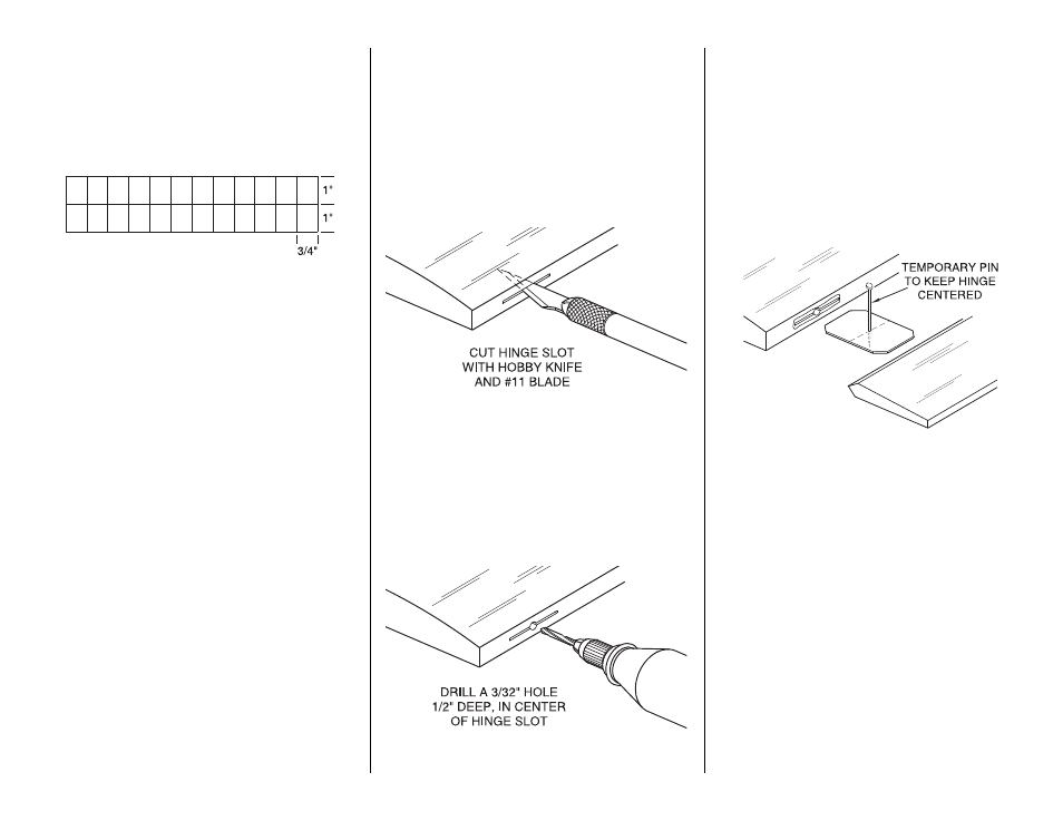
A.
Cut the hinge slot using a #11 blade in a
standard #1 knife handle. The CA hinges provided
have a thickness that fits this type of slot very well.
Trial fit the hinge into the slot. If the hinge does not
slide in easily, work the knife blade back and forth
in the slot a few times to provide more clearance (it
is really the
back edge
of the blade that does the
work here in widening the slot).
B. Drill a 3/32" hole, 1/2" deep, in the center of
the hinge slot.
If you use a Dremel MultiPro
®
for
this task, it will result in a cleaner hole than if you
use a slower speed power or hand drill. Drilling the
hole will twist some of the wood fibers into the slot,
making it difficult to insert the hinge, so you should
reinsert the knife blade, working it back and forth a
few times to clean out the slot.
Note:
When hinging the rudder and elevator which
use torque rods, use a toothpick to force epoxy
down the hole drilled for the torque rod. In the case
of the rudder, be sure not to let glue get into the
bearing tube.
C. Insert the hinges and install the control surface.
Verify the left-right positioning of the control
surface, and close up the hinge gap to 1/32" or
less. It is best to leave a very slight hinge gap,
rather than closing it up tight, to help prevent the
CA from wicking along the hinge line. Make sure
the control surface will deflect to the recommended
throws without binding. If you have cut your hinge
slots too deep, the hinges may slide in too far,
leaving only a small portion of the hinge in the
control surface. To avoid this, you may
insert a
small pin
through the center of each hinge, before
installing. This pin will keep the hinge centered
while installing the control surface. Remove the
pins before proceeding.
37