Top Flite TOPA0101 User Manual
Page 19
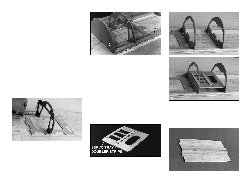
FUSELAGE TOP
NOTE:
The 1/8" die-cut plywood formers are
stamped only with the necessary portion of their
name (F-3B is stamped 3-B).
IMPORTANT:
All formers should be installed with
the
STAMPED IDENTIFICATION NUMBER
FACING FORWARD.
This is necessary to line up
the pushrod holes.
❏
1. Cut out the
Top View
of the fuselage. Tape it
to the building board and cover it with waxed paper.
❏
2. Pin the 1/8" die-cut forward frame accurately
over the plan. Be sure the outline fits the plan
exactly as this establishes the engine offset
thrust angle.
NOTE:
Use a small triangle to hold all formers
vertical while gluing. Any small warps or twists in
the formers can be taken out when the 3/16" sq.
stringers are glued in place.
❏
3. Glue
F-3
into the forward half of the slot in
the middle of the forward frame.
❏
4. Glue
F-2
to the forward edge of the forward
frame. It is centered by the interlocking tab.
❏
5. Separate the two 42" long shaped balsa
main fuselage stringers
by running a knife
vertically against the edge where they are joined.
Sand the edges if necessary.
❏
6. Position the
main fuselage stringers
in the
former notches so the ends protrude about 1/16"
forward of F-2. Notice that the 1/8" slots in the
main fuselage stringers are more toward the
bottom of the fuse (toward the table). Glue the
stringers to F-2, F-3 and the forward frame
❏
7. Glue
F-4
in place at the aft end of the forward
frame. The notch at the center of F-4 engages the
tab on the forward frame (see photo at step 10).
❏
8. Drill 3/16" holes where indicated by punch
marks in
F-5, F-7, F-8 and F-10
. The pushrods will
be installed through these holes later. Check that
all pushrod holes are offset slightly to the plane’s
left. These holes should line up for a virtually
straight shot.
❏
9. Check your servos for fit in the 1/8" die-cut
servo tray
. Make modifications if necessary. Glue
the 1/8" die-cut plywood
servo tray doubler strips
to one side of the servo tray as shown. These will
stiffen the tray and give the servo mounting screws
extra material to bite into.
❏
10. Position
F-5
over the plan. Key the servo tray
in place as in the photo. Notice that the servo tray
doublers are facing up. Glue F-5 to the main stringer.
Remove the servo tray and apply medium CA to the
mating surfaces. Put the servo tray back in position.
❏
11. Glue the two halves of the die-cut 1/8" balsa
cockpit deck (CD)
together.
19