Top Flite TOPA0101 User Manual
Page 6
SUPPLIES AND TOOLS NEEDED
❏
2 oz. Thin CA Adhesive (GPMR6003)
❏
2 oz. Medium or Thick CA (GPMR6009)
❏
6-Minute Epoxy (GPMR6045)
❏
30-Minute Epoxy (GPMR6047)
❏
Hand or Electric Drill
❏
Drill Bits: 1/16", 3/32", 1/8", 5/32", 3/16",
13/64", 7/32", 1/4", and 5/16"
❏
Soldering Iron & Silver Solder
❏
Sealing Iron (TOPR2100)
❏
Heat Gun (TOPR2000)
❏
Hobby Saw (Razor Saw)
❏
Hobby Knife, #11 Blades
❏
Plier
❏
Screwdrivers (Phillips & Flat Head)
❏
T-Pins (HCAR5150)
❏
Straightedge
❏
Short Ruler
❏
Masking Tape (required for construction)
❏
Sandpaper (coarse, medium, fine grit)*
❏
Bar Sanders (see below)
❏
Waxed Paper
❏
Lightweight Balsa Filler (HCAR3401)
❏
1/4-20 & 8-32 Tap, (GPMR8105) (GPMR8103)
❏
Tap Wrench
❏
Isopropyl Rubbing Alcohol (70%)
❏
Rotary tool (Dremel
®)
) or similar (optional)
On our workbench, we have four 11"
Great
Planes
®
Easy-Touch
™
Bar Sanders
, equipped
with #50, #80, #150 and #220-grit sandpaper.
This setup is all that is required for almost any
sanding task. Custom sanding blocks can be
made from balsa for sanding hard to reach spots.
We also keep some #320-grit wet-or-dry
sandpaper handy for finish sanding before
covering. Great Planes
Easy-Touch Bar
6
DECISIONS YOU MUST MAKE
EARLY IN THE
BUILDING SEQUENCE
ENGINE AND MOUNT SELECTION
The recommended engine size range is as follows:
.60 to .90 cu. in. 2-stroke
.90 to 1.20 cu. in. 4-stroke
NOTE:
The smaller engines in the range provide
more than enough power to fly the Corsair well. Do
not hesitate to use them.
The instructions show an OS
®
.61 2-stroke engine
side mounted at a 45 degree inverted position. It
also shows a Top Flite internal muffler
(TOPQ7915). This power package works very well.
Most .61 2-stroke engines will fit in the supplied
EM60120 engine mount.
The instructions also show the installation of an OS
1.20 4-stroke engine. Even though it is shown
mounted inverted, it could also be mounted upright
or on its side; the decision is yours. Flexible exhaust
systems are available for most 4-stroke engines and
there is more than enough room inside the Corsair’s
cowl to route the exhaust out the bottom. You would
also have to change the cowl mounting. The engine
is shown on the plans mounted to a JT-122 SV
isolation mount which may no longer be available.
The supplied EM60120 mount will fit the O.S. 1.20.
FULL COCKPIT
(Optional)
You must decide before you build the fuselage if
you will be adding the optional full cockpit kit
(TOPQ8404) to your Corsair. If you are undecided,
you should build it as though you are going to
install it. That way you can add it at a later time
should you want to.
FLAPS
You must decide early in the building process if
you are going to use operating wing flaps. These
are not required but do add to the Corsair's
appearance and flyability. The flaps as described
in this manual work very well, giving super stable
slow flight with virtually no trim changes. Obviously
there is some extra work and craftsmanship
required to fit operating flaps to the model. If you
use operating flaps, you will need to have (2)
standard servos and small Robart hinge points
(ROBQ2508) available during construction.
RETRACTS
You will need to decide early whether you intend to
use retractable landing gear in your Corsair.
Robart 100 degree rotating retracts (ROBQ1815)
were used in the prototypes and the rib spacing
and mounts in the kit are designed to accept them.
Century Jet Models 90 degree rotating retracts
(CJMQ3055) will also work as well. Other retracts
have not been tested.
COMMON ABBREVIATIONS USED IN
THIS BOOK AND ON THE PLANS:
Deg. = Degrees
Ply
= Plywood
Elev = Elevator
Rt
= Right
Fuse = Fuselage
Stab = Stabilizer
LE
= Leading Edge
TE
= Trailing Edge
(front)
(rear)
LG
= Landing Gear
"
= Inches
Lt
= Left
Tri
= Triangle
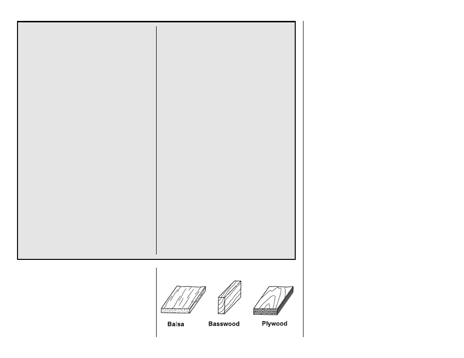
TYPES OF WOOD