Conf, Lpm -1- 3.0, Reference pressure – TeeJet 844-AB Sprayer Control User Manual
Page 13: Reference flow
11
98-70007-EN R4
844-AB
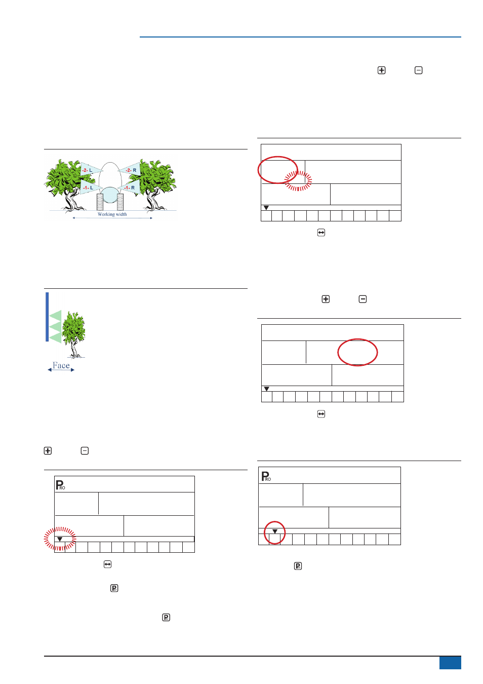
Reference flow rate per section
AB mode – The flow rate for each section of the sprayer must be
input into the 844-AB console so that the necessary adjustments
can be made when boom sections are shut off. The console is
programmed to treat the left and right boom sections as symmetrical;
therefore the console treats the flow rate for the lower left section
(L1) identically to the flow rate of the lower right section (R1). The
flow rate entered for section 1 will serve as reference flow for L1 and/
or R1.
Figure 34: AB flow rate illustration
HC mode – The flow rate for a single nozzle must be input into the
844-AB console so that the necessary adjustments can be made
when boom sections are shut off. If several different nozzles are
mounted to spray on a face, they should be considered as ONE
nozzle and the total flow should be programmed.
Figure 35: HC flow rate illustration
1. Select section
Up to twelve preset flow configurations can be entered into the
844-AB. The presets are represented by the numbers “1-12” at the
bottom of the display. The arrow symbol indicates which preset is
being programmed.
Select which preset flow configuration to programme. Use the Plus
or Minus keys to toggle through the twelve presets.
Figure 36: Preset selection
SEL
ConF
1
2 3
4 5
6 7
8 9
10 11
12
Press the Auto/man key to setup the reference pressure and
reference flow of the selected preset.
Press the Programme key to advance to the next programme
step in System setup mode. It is not necessary to programme all
twelve presets unless they are to be used. Programme the number of
presets required. Press the Programme key again to continue in
System setup mode.
2. Reference pressure
Before entering the reference flow, determine the pressure at which
the flow will be referenced. Use the Plus or Minus keys to
adjust the value of the pressure Bar to be used as flow reference.
The pressure selected to reference flow is not critical (any pressure
can be used). Select a pressure that is close to normal operating
pressure or select a pressure from the flow rate chart for the nozzles
being used.
Figure 37: Reference pressure
REF
1
2 3
4 5
6 7
8 9
10 11
12
3.0
Bar
Press the Auto/man key to advance to the reference flow for
current preset section.
3. Reference flow
Calculate (add) the flow rates at the referenced pressure from all
nozzles on the current preset section (left or right should be the
same). Enter the total flow rate in litres/min. for the current preset
section. Use the Plus or Minus keys to adjust the value.
Figure 38: Reference flow (Section one entry)
1.36
1
2 3
4 5
6 7
8 9
10 11
12
LPm
-1-
3.0
Bar
Press the Auto/man key to return to the select section option.
Next section
Repeat steps 1-3 for all sections as needed.
Figure 39: Reference flow (Section two entry)
0.85
1
2 3
4 5
6 7
8 9
10 11
12
LPM
-1-
3.0
Bar
Once programming is complete for all presets, press the
Programme key to advance to the next programming step.