Operation mode, Main setup mode, Isobus job computer : boompilot – TeeJet BOOMPILOT JOB COMPUTER User Manual
Page 7: Main setup mode menu structure, The table below outlines the additional menus
3
98-05210 R0 UK
OVER
VIE
W
SE
TUP
APPENDIX
GE
TTING ST
AR
TED
OPER
ATION
ISOBUS Job Computer : BoomPilot
®
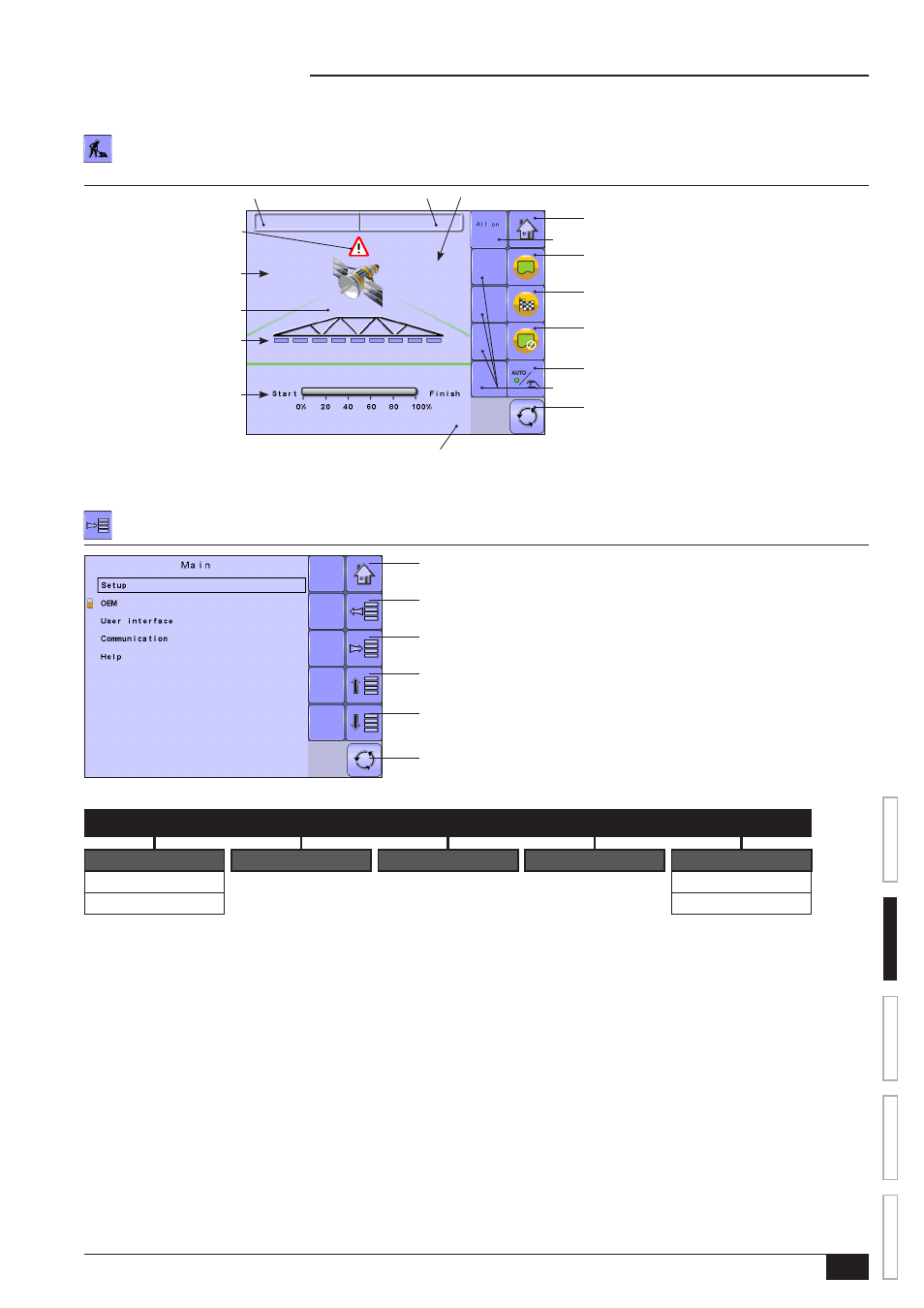
Operation Mode
Information on the Operation screen will vary depending on the parameters set by the user and the OEM.
Figure 2-3: Operation Mode
1 . 7 7 B . a r e a
5 . 2
0 . 0
0 : 0 0 h h : m m
h a
2
k m / h
N o G P S
Total Area Bounded
Speed
GPS Information
Alert Warning
Applied Area
Boom Sections
Bounded Area Application Status
Remaining Application Time
ECU ID Number
All Sections On Key
Extra Key Spaces
Home Key
Start Boundary Key
No Boundary Key
Auto/Manual Mode Key
Master Screen Key
Finish Boundary Key
Main Setup Mode
The main setup menu contains five options. Each of these options either directly access settings or additional menus.
Figure 2-4: Main Setup Screen
Home Key
Back One Screen
Up One Selection
Down One Selection
Master Screen Key
Forward One Screen
The table below outlines the additional menus.
MAIN SETUP MODE MENU STRUCTURE
|
|
|
|
|
Setup
OEM
User Interface
Communication
Help
GPS Setup
Diagnostic
Machine Setup
The OEM setup menu is password protected and the
settings in this menu are directly related to the fitted OEM
equipment.
About
NOTE: Select functions may not be visible due to OEM settings, available equipment or sensors.