Type of pipe (field-supplied) (cont'd), Joints/seals, Pipe diameter and length - ft (m) – Reznor SFT Unit Installation Manual User Manual
Page 8: Support, Clearance
Form RZ -NA-I-SFT, Mfg No. 173474 (Rev 6), Page 7
Horizontal Vent
Terminal/Combustion
Air Package
(Option CC6)
includes:
Instructions and Requirements for Installing a Horizontal Vent Terminal/Combustion Air
Inlet (Requires Concentric Adapter Kit, Option CC6)
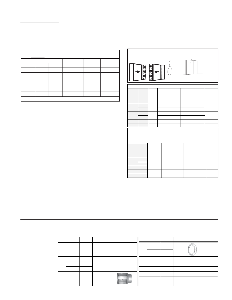
2. Type of Pipe (field-supplied) (cont'd)
Reducer
Enlarger
Airflow
Airflow
Either collar
or smaller
diameter pipe
Taper-type Connector
Secure joints with sheetmetal
screws and seal.
Figure 5 - Use taper-type connections (see where
they are required below)
S ize
S FT
Inlet
Air
Pipe
Air Inlet
Collar on
Concentric
Adapter
Reducer required
to join concentric
adapter collar and
pipe
Reducer required
to join heater
collar and pipe
Inlet Air
Collar at
Heater
3" dia
4" to 3" Reducer
None
4" dia
None
4" to 3" Reducer
60-125 4" dia
4" dia
None
None
4" dia
150-250 5" dia
5" dia
None
None
5" dia
300
6" dia
6" dia
None
None
6" dia
45
4" dia
3" dia
A taper-type connector is always required in the indoor portion of the INLET
AIR PIPE on Model SFT 45. When using 3" pipe, install the reducer at the
concentric adapter. When using 4" pipe, install the reducer at the heater. Other
sizes do not require a taper-type connection in the inlet air pipe run.
run is different from the connections at either the heater or the con-
centric adapter box, the joint must be made with a taper-type pipe
connector.
When the diameter change is at the heater, install the connector at
the collar or no more than 6" (152mm) from the heater.
When the diameter change is at the concentric adapter box, install
the connector no more than 6" (152mm) from the opening or collar
on the concentric adapter box.
Concentric Pipes (the vent pipe runs through the concentric adapter
extending internally concentric through the outdoor portion of the com-
bustion air pipe) - Sizes 45 - 250 require 6" diameter combustion air pipe
for the outdoor portion and a 4" vent pipe through the concentric adapter
to the terminal; Size 300 requires an 8" diameter combustion air pipe for
the outdoor portion and a 5" diameter vent pipe through the concentric
adapter to the terminal. Refer to the installation instructions for the con-
centric adapter kit for length requirements.
4. Joints/Seals
In Pipe Runs - provide pipe as specified in Requirement No. 2 and make
joints as follows:
•
If using single wall, 26-gauge or heavier galvanized pipe, secure
slip-fit pipe connections using sheetmetal screws or rivets. Seal all
joints. Seal combustion air pipe with pressure sensitive tape ordi-
narily used for warm-air ductwork. Wrap two full turns around each
joint. Seal flue exhaust pipe with either tape suitable for 550°F (such
as Option FA1, P/N 98266) or high-temperature (450°F) silicone seal-
ant.
•
If using Category III vent pipe, follow the pipe manufacturer's in-
structions for joining and sealing vent pipe sections.
In Concentric Pipes (outdoor portion) from the Adapter Box to Air
Inlet and Vent Terminal - Follow the instructions for concentric adapter
kit (pages 7 - 9 for a horizontal system or pages 10 - 110 for a vertical
system).
Joints Requiring Taper-type Connections (See Figure 5 and Tables
that follow) - When the diameter of the pipe in the inlet air or vent pipe
Combustion Air Inlet Pipe Between the Heater and the Concentric
Adapter - Sealed, single-wall galvanized pipe is recommended.
Combustion Air Pipe Between the Adapter Box and the Combustion
Air Inlet - The vent pipe is internally concentric to the combustion air
pipe; use single-wall galvanized pipe for the combustion air pipe.
3. Pipe Diameter and Length - ft (M)
Maximum Pipe Length from Heater to Concentric
Adapter - minimum length is five feet (1524 mm)
Model
Pipe Diameter
Maximum
90° Elbow
45° Elbow
SFT
Vent
Inlet Air
Length
Equals*
Equals*
45
3" or 4"
3"
30 ft (9.1M)
5 ft (1.5M) 2.5 ft (.8M)
60, 75,
4" or
4"
40 ft
5 ft
2.5 ft
100, 125
5"
(12.1M)
(1.5M)
(.8M)
150, 200
5"
5"
40 ft (12.1M) 5 ft (1.5M) 2.5 ft (.8M)
250
5"
5"
50 ft (15.2M) 5 ft (1.5M) 2.5 ft (.8M)
300
6"
6"
50 ft (15.2M) 5 ft (1.5M) 2.5 ft (.8M)
*Reduce maximum length by this amount for each elbow.
Qty
Size
P/N
Description
1
45-125 157157
150-250 157158
300
82131
1
45-125 155118
150-250 155392
300
68404
1
45-250 155096 Screened
300
53316 Exhaust Assy
Complete Horizontal Vent Kit
(Same as Opt ion CC6)
Concent ric Adapter Box
Assemby (See Figure 3A)
Qty
S ize
P/N
Description
1
45-250 151755 Inlet
300
124940 Guard
4
45-300
37661
#10-16 x 1/2" lg Screws to
att ach the inlet guard
1
45-250 164492 4" I.D. Rubber Seal
1
300
164493 5" I.D. Rubber Seal
1
45-300
53335
T ube of High T emperature
(450°F) Silicone Sealant
S FT
S ize
Vent
Pipe
Run
Venter
Collar
on
Heater
Reducer required
to join venter collar
and p ip e
Tap er-ty p e
connection required
to join different
diameter vent p ip es
Vent Pip e
through
Adap ter
Box
3" dia
4" to 3" Reducer
3" to 4" Enlarger
4" dia
None
None
4" dia
5" to 4" Reducer
None
5" dia
None
5" to 4" Reducer
150-250 5" dia
5" dia
None
5" to 4" Reducer
4" dia
300
6" dia
6" dia
None
6" to 5" Reducer
5" dia
Taper-typ e connector(s) required in the VENT PIPE RUN
4" dia
4" dia
60-125
45
4" dia
5" dia
5. Support
Support horizontal runs every six feet (1829mm); do not rely on the
heater or the adapter box for support of either horizontal or vertical
pipes. Use non-combustible supports on vent pipe.
6. Clearance
Do not enclose the vent pipe or place pipe closer than 6" (152mm)
to combustible material.