Venting and combustion air (cont'd), Installation requirements for option cc2, Installation instructions for option cc2 – Reznor SFT Unit Installation Manual User Manual
Page 11
Form RZ -NA-I-SFT, Page 10
9. Venting and Combustion Air (cont'd)
Installation Requirements for Option CC2
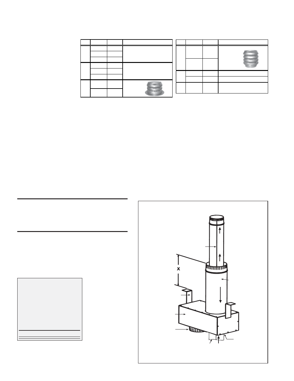
Collar for
combustion
air pipe.
Vent Pipe - when a taper-type
reducer is required in the
vent pipe; it must be no more
than 6(152mm) from the box.
Seal the seam in
the vent pipe.
Concentric
Adapter Box
Combustion
air pipe
Field-supplied
mounting brackets
Install seal
in vent pipe
opening
Vent Flow
Combustion Air
Flow
Install the vent pipe
by inserting it into
the terminal side of
the box and pushing
it out through the
seal on the heater side
NOTE: Be sure
vent flow direction
is correct.
Field-supplied installation requirements:
•
Thimble (a thimble is not required if roof is of non-combus-
tible construction)
•
Flashing
•
Vent pipes (see requirements on pages 6-7)
•
Combustion air pipes (see requirements on page 7)
•
Mounting brackets for concentric adapter box (or box may be
mounted flush, depending on construction)
•
Joint connection reducers and/or enlargers (see requirements
on page 7)
Installation Instructions for Option CC2
1. Determine the location for the vent terminal on the roof,
allowing room for the concentric adapter box inside. A thimble
may or may not be required depending on building construction
and/or local codes. Prepare a hole through the roof for the com-
bustion air pipe. The air inlet pipe must be flashed or sealed to
the roof. Flashing is to be supplied by the installer as required by
roof construction and/or codes.
WARNING: All vent terminals must be positioned
or located away from fresh air intakes, doors and
windows to preclude combustion products from
entering occupied space. See Hazard Levels, page
2.
2. Prepare the concentric adapter box.
2a) Determine whether field-supplied brackets are required.
If used, attach brackets securely; do not leave any unsealed
holes in the adapter box. If brackets are not used, when in-
stalled the box should be against the roof.
2b) Install the rubber seal and the vent pipe. Locate the vent
pipe opening and place the rubber seal around and over the
edge of the metal.
Determine the length of
the section of vent pipe
by adding the require-
ments. The vent pipe
must extend a maximum
of 6" (152mm) on the
heater side (if a reducer
is required); plus 6"
(152mm) through the
box; plus bracket length;
plus the width of the roof;
plus the length of the
outer inlet air pipe; plus
a minimum of 22"
(559mm).
Lubricate the seal and pipe with liquid soap or a rubber lubri-
cant. (Installation Tip: Spray cooking oil works well as a lu-
7A
"X" is the length of combustion
air pipe required through and
above the roof
"X" must equal roof thickness
plus clearance required for
anticipated snow plus ridge and/or
parapet
"X" must not
exceed 60"
(1524mm)
bricant for this task.) Being sure the pipe is in the proper flow direction,
slide the end through the box and push it out through the rubber seal.
Push evenly using caution not to displace the seal from its position on
the edge of the hole. If the rubber seal moves, slide the pipe back slightly,
re-position the seal, and slide the pipe through again. When the vent pipe
is in its final position, re-check the seal to be sure that it has not rolled in.
Adjust the pipe and seal until the seal is in the correct position on the
edge of the hole and tight to the entire circumference of the pipe.
Position the vent pipe so that it will protrude a minimum of 22" (559mm)
past the end of the combustion air pipe. See Figure 7A.
If a taper type connection is required in the vent run, no more than 6"
(152mm) of vent pipe should extend out the heater side of the adapter
box.
2c) Attach the outside portion of the combustion air pipe to the box.
Determine the length of the combustion air pipe so that dimension "X"
(Figure 7A) is equal to the roof thickness, plus snow depth and ridge or
parapet clearance, but does not exceed 60" (1524 mm). Attach the com-
bustion air pipe to the collar with sheetmetal screws being careful not to
penetrate the vent pipe.
Worksheet - Determine Length of
Vent Pipe through the Box
inches mm
Heater Side (max if +
6
152
different diameters)
Width of Box
+
6
152
Bracket Length
+
__
___
Width of Roof
+
__
___
Inlet Pipe Height
+
__
___
Terminal Side (min) +
22
559
Length of Pipe
=
Instructions and Requirements for Installing a Vertical Vent Terminal/Combustion Air Inlet
(Requires Concentric
Adapter Kit,
Option CC2)
Q ty
Siz e
P/N
De scripti on
1
45-125
157155
150-250 157156
300
54444
1
45-125
155118
150-250 155392
300
68404
1
45-250
155631 Exhaust
300
53326 T erminal
Complete Vert ical Vent Kit
(Same as Opt ion CC2)
Concent ric Adapter Box
Assembly (See Figure 3A)
Q ty
Siz e
P/N
De scripti on
1
45-250
155635
Combustion
300
53330
Air Inlet
1
45-250
164492 4" I.D. Rubber Seal
300
164493 5" I.D. Rubber Seal
1
45-300
53335
T ube of High T emperat ure
(450°F) Silicone Sealant