Electrical supply and connections, Thermostat and connections, Fan motor – Reznor SFT Unit Installation Manual User Manual
Page 14
Form RZ -NA-I-SFT, Mfg No. 173474 (Rev 6), Page 13
Instructions for Derating a Heater by Adjusting Manifold
Pressure (The heater must be factory-equipped for sea
level operation.)
1. Check the rating plate to be certain that the heater is equipped for
sea level operation. Do not attempt to derate by manifold gas pres-
sure adjustment if the heater is factory equipped for high alti-
tude.
2. Determine the required manifold pressure for the elevation where
the heater will be operating. If unsure of the elevation, contact the
local gas supplier.
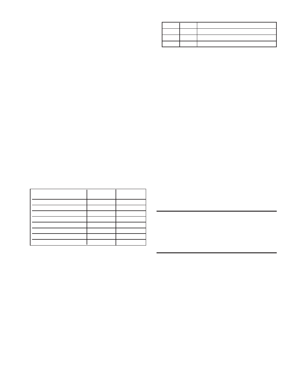
Manifold Pressure Settings by Elevation
Altitude
Natural Gas
Propane Gas
Feet
Meters
(inches W.C.)
(inches W.C.)
0- 2000
1-610
3.5
10.0
2001-3000
911-915
2.8
7.7
3001-4000
916-1220
2.5
7.1
4001-5000
1221-1525
2.3
6.4
5001-6000
1526-1830
2.1
5.8
6001-7000
1831-2135
1.9
5.2
7001-8000
2136-2440
1.7
4.6
8001-9000
2441-2745
1.5
4.1
3. With the manual valve positioned to prevent flow to the main burn-
ers, connect a manometer to the 1/8” pipe outlet pressure tap in the
valve. Use a fluid-filled manometer that is readable to the nearest
tenth of an inch w.c.
4. Remove the cap from the pressure adjusting screw and adjust the
manifold pressure to the pressure setting selected from the table.
Cycle the main burners once or twice to properly seat the adjust-
ment spring in the valve.
Re-check the pressure. If necessary, re-adjust the pressure. When
the pressure is correct, remove the manometer and replace the cap.
Check for leaks at the pressure tap fitting.
5. With the heater operating determine that the inlet pressure to the
heater for natural gas is between 5 and 14 inches. w.c. and for pro-
pane between 10 and 14 inches w.c. Take this reading as close as
possible to heater (Most heaters are now equipped with gas valves
that have an inlet pressure tap.) If the inlet pressure is not within
the specified range, the inlet pressure must be corrected and Steps
3 and 4 repeated.
6. If altitude is above 6000 ft (1830M), verify that the pressure switch
has been changed.
Instructions on How to Check Manifold
Pressure (can only be done after heater is
installed):
1) With the manual valve positioned to prevent flow to the main burn-
ers, connect a manometer to the 1/8" pipe outlet pressure tap in the
valve. NOTE: A manometer (fluid-filled gauge) is recommended rather
than a spring type gauge due to the difficulty of maintaining calibra-
tion of a spring type gauge.
2) Open the valve and operate the heater. Measure the gas pressure to
the manifold. Normally adjustments should not be necessary to the
factory preset regulator.
If adjustment is necessary, set pressure to correct settings by turning
the regulator screw IN (clockwise) to increase pressure. Turn regulator
screw OUT (counterclockwise) to decrease pressure.
Derating by Manifold Pressure Adjustment for
High Altitude Operation
If the heater is being installed above 2000 ft (610M) and it was deter-
mined in Paragraph 5 that derating by manifold pressure adjustment is
permissible, follow the instructions below.
11. Electrical Supply and
Connections
All electrical wiring and connections, including electrical grounding
MUST be made in accordance with the National Electric Code ANSI/
NFPA No. 70 (latest edition) or, in Canada, the Canadian Electrical
Code, Part I-C.S.A. Standard C22.1. In addition, the installer should
be aware of and comply with any local ordinances or gas company
requirements.
Check the rating plate on the heater for the supply voltage and current
requirements. A separate line voltage supply should be run directly
from the main electrical panel to a fused disconnect switch located
near the heater. All external wiring must be within approved conduit
and have a minimum temperature rise of 60°C. Conduit from the dis-
connect switch to the heater must be run so as not to interfere with the
service panels of the heater.
The electrical supply and control wiring enter at the rear of the heater
and connect to the terminal board or the integrated ignition control
module. The 115 volt supply wiring connects to pigtails on the lower
portion of the terminal board. The terminal strip for 24 volt thermostat
connections is located on the upper portion of the ignition control
module. See Figure 9.
Consult the wiring diagram supplied with your heater. A typical wiring
diagram is on page 15.
CAUTION: If any of the original wire as supplied
with the appliance must be replaced, it must be
replaced with wiring material having a
temperature rating of at least 105°C, except for
limit control and sensor lead wires which must
be 150°C. See Hazard Levels, page 2.
12. Thermostat and Connections
A thermostat is not standard equipment but is an installation require-
ment. Use either an optional thermostat available with the heater or a
field-supplied 24-volt thermostat. Install according to the thermostat
manufacturer's instructions.
Make sure that the heat anticipator setting on the thermostat is in ac-
cordance with the amperage value noted on the wiring diagram of your
heater.
13. Fan Motor
The fan motor is equipped with thermal overload protection of the au-
tomatic reset type. Should the motor refuse to run, it may be because of
improper current characteristics. Make certain that the correct voltage
is available at the motor.
High Altitude Combustion Air Pressure Switches
SFT
P/N
Description
45-75
173316
Orange Label, -.55", #PPS10143-2908
100-125 173315
Gray Label, -.35", #PPS10143-2907
150-300 173312
White Label, -.60", #PPS10143-2904
7. Find the Manifold Pressure Adjustment label in the plastic bag that
contained these instructions. Using a permanent marker, fill-in the
pressure setting. Adhere the label on the heater near the gas valve
so that it is conspicuous to someone servicing the valve and/or the
heater.